
Vehicle Stability And Steerability Control Via Electronic Torque Distribution

a technology of electronic torque distribution and steering control, which is applied in the direction of driver input parameters, non-deflectable wheel steering, underwater vessels, etc., can solve the problems of reducing the longitudinal performance of the vehicle, the sum of the torque supplied to the two axles is somewhat less than what the powertrain supplies, and the mechanical system is incapable of achieving a change in torque distribution sufficiently fast, etc., to achieve the effect of reducing the electric energy supplied to the rear axle motor, increasing torque and decreasing torqu

Active Publication Date: 2011-10-20
FORD GLOBAL TECH LLC
View PDF2 Cites 48 Cited by
  • Summary
  • Abstract
  • Description
  • Claims
  • Application Information

AI Technical Summary

Benefits of technology

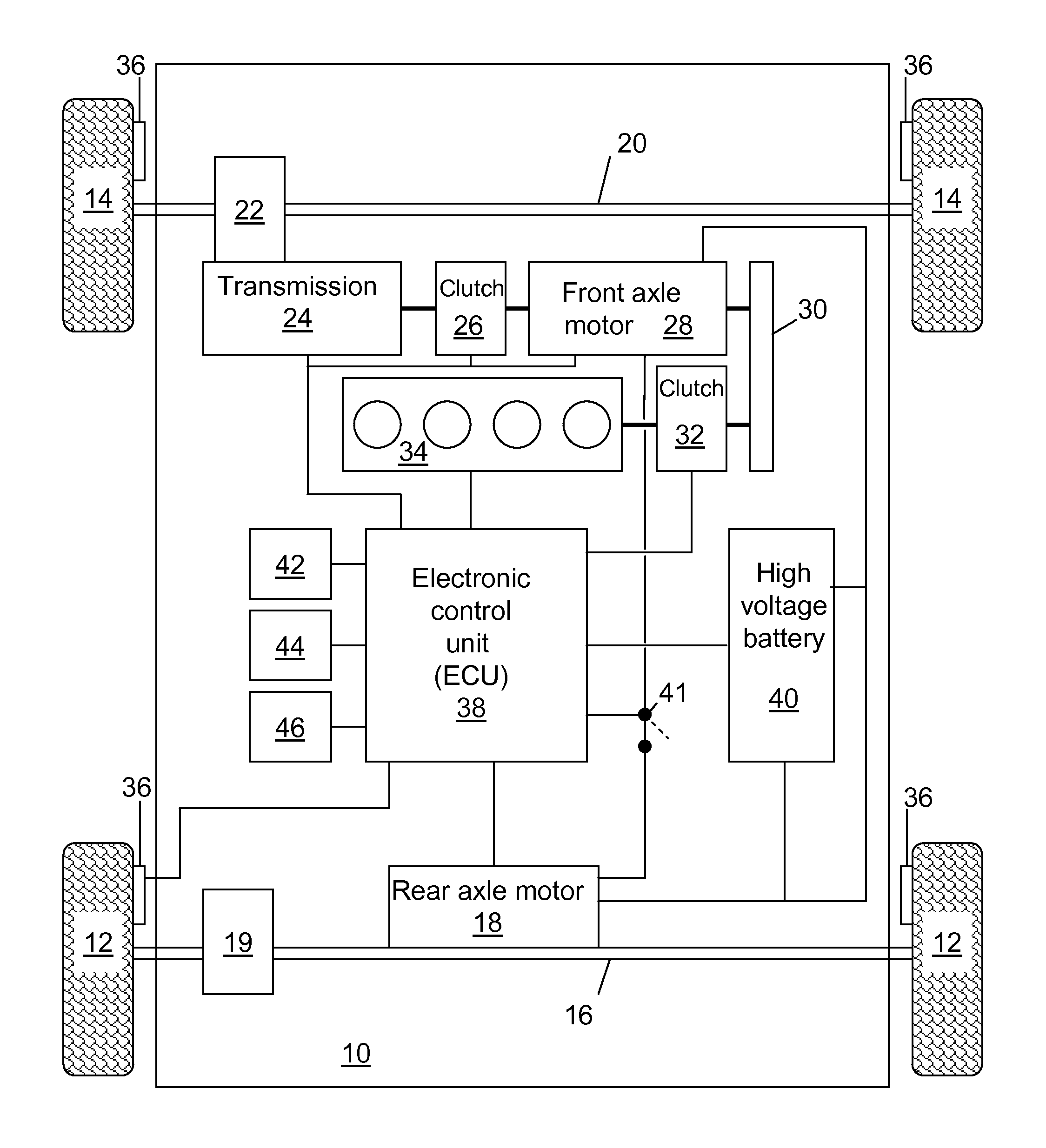
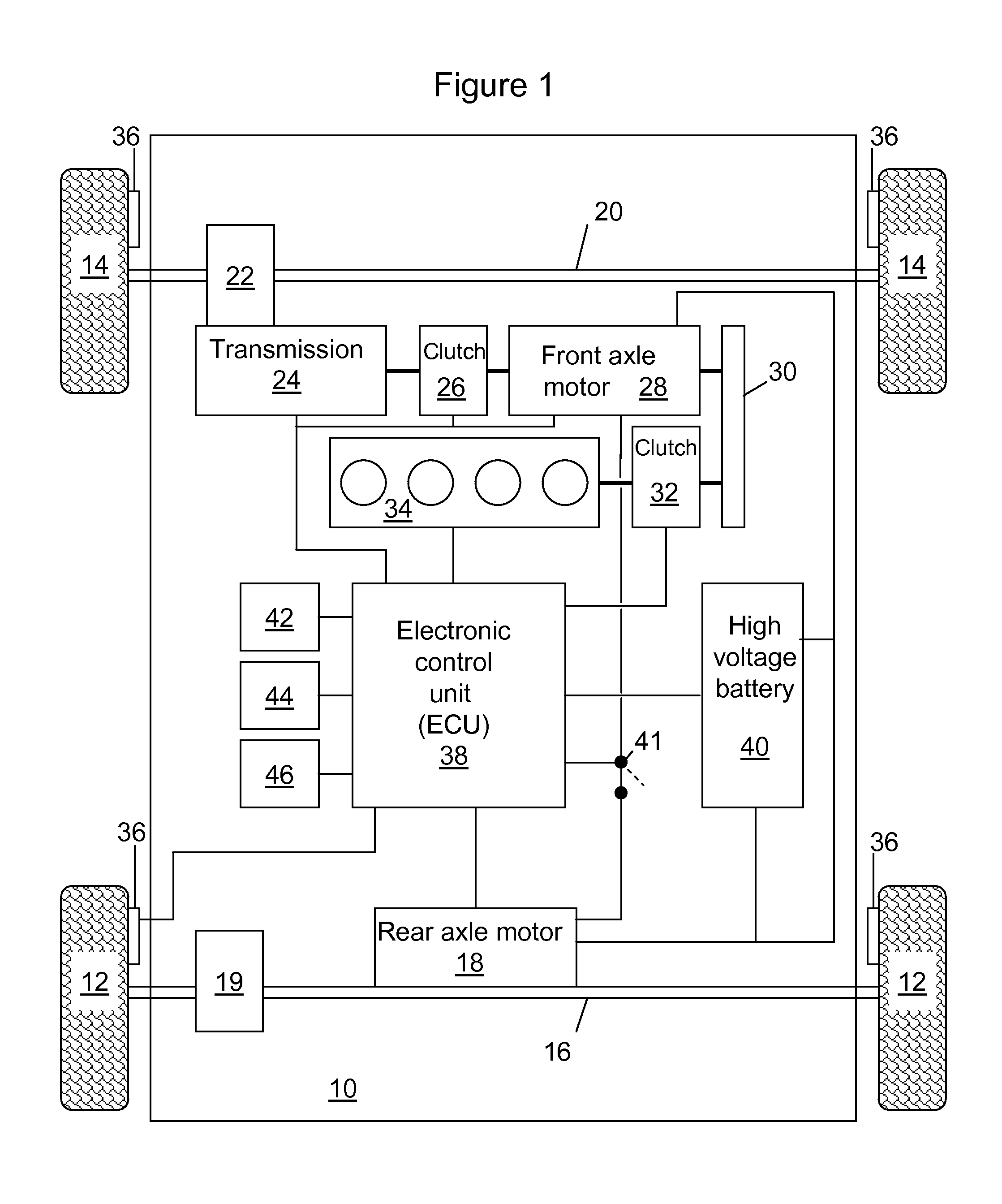
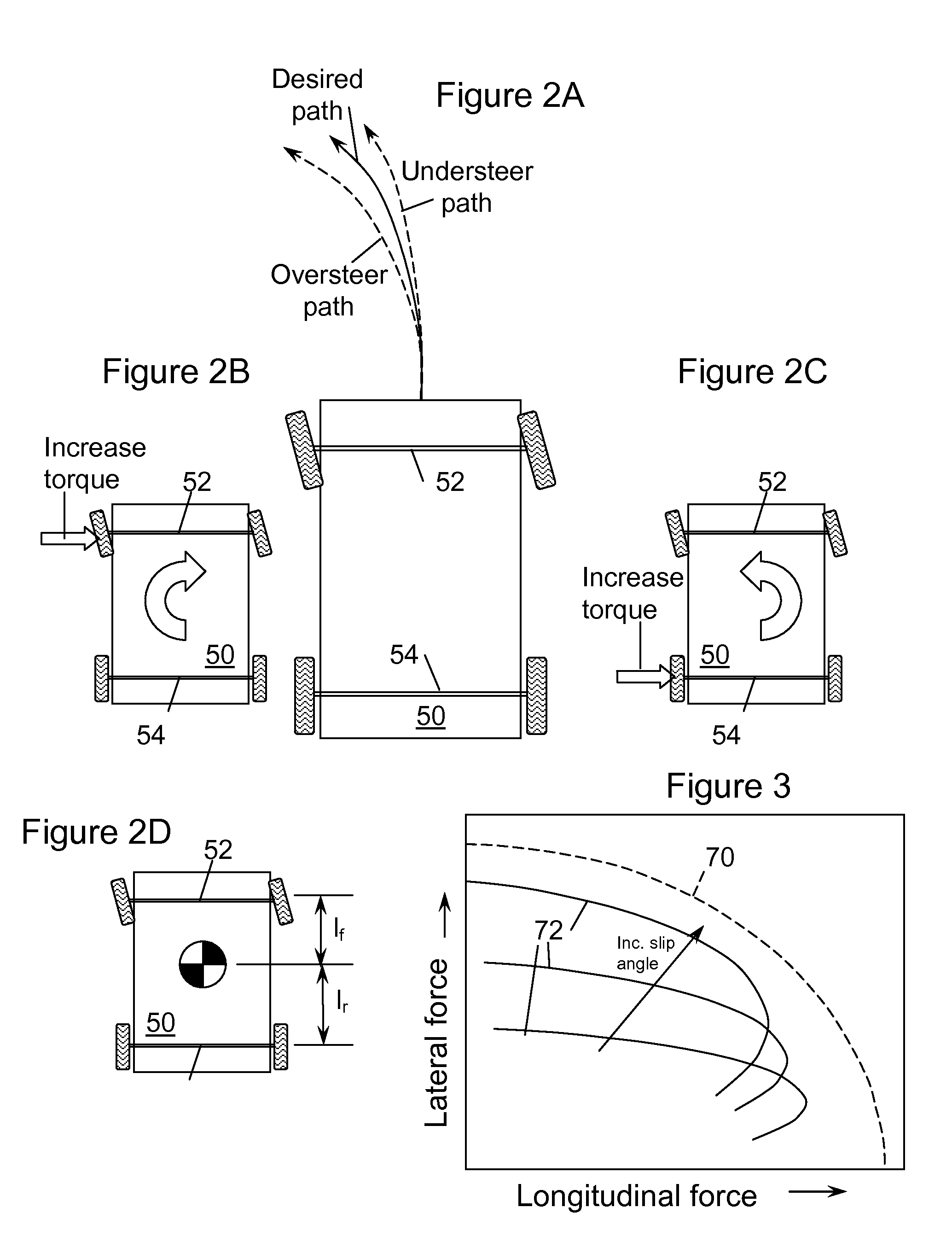
[0010]The ECU commands a front axle motor to increase torque supplied to the front axle and the rear axle motor to decrease torque supplied to the rear axle when the vehicle is in an oversteer situation. The ECU commands the rear axle motor to increase torque supplied to the rear axle and the front axle motor to decrease torque supplied to the front axle when the vehicle is in an understeer situation. If a motor is supplying a positive torque to the axle to which it is coupled, the torque can be decreased as desired down to zero, at which point further decreases in torque are provided by operating the motor as a generator.

Problems solved by technology

There is a delay between the time that the traction loss is detected and the mechanical coupler actually redistributes torque from the slipping tires of the primary axle to the wheels of the secondary.
In situations such as encountering a patch of ice, in which road surface conditions can change very rapidly, a mechanical system is incapable of effecting a change in torque distribution sufficiently fast.
Furthermore, due to frictional losses and torque transfer capability through the mechanical coupler, the sum of the torques supplied to the two axles is somewhat less than what the powertrain supplies to the primary axle.
Thus, when the mechanical coupler is invoked, there is a drop in longitudinal performance of the vehicle, which may be particularly noticeable during acceleration.
The ability of a mechanical system to redistribute torque may be limited in torque and further hampered by environmental influences, such as temperature.
However, as with the desire to redistribute torque for a forward traveling vehicle encountering insufficient or excessive turning moment, the mechanical coupler reacts more slowly than desired and the torque redistribution is less accurately controlled in the coupler such that the operator of the vehicle notices a uncomfortable change in vehicle turning property.

Method used


Image

  • Vehicle Stability And Steerability Control Via Electronic Torque Distribution
  • Vehicle Stability And Steerability Control Via Electronic Torque Distribution
  • Vehicle Stability And Steerability Control Via Electronic Torque Distribution

Examples


Embodiment Construction

[0018]As those of ordinary skill in the art will understand, various features of the embodiments illustrated and described with reference to any one of the Figures may be combined with features illustrated in one or more other Figures to produce alternative embodiments that are not explicitly illustrated and described. The combinations of features illustrated provide representative embodiments for typical applications. However, various combinations and modifications of the features consistent with the teachings of the present disclosure may be desired for particular applications or implementations. Those of ordinary skill in the art may recognize similar applications or implementations consistent with the present disclosure, e.g., ones in which components are arranged in a slightly different order than shown in the embodiments in the Figures. Those of ordinary skill in the art will recognize that the teachings of the present disclosure may be applied to other applications or impleme...


PUM


Abstract

A system for distributing propulsion to front and rear axles of a vehicle includes: a front axle motor coupled to the front axle and a rear axle motor coupled to the rear axle. An electronic control unit (ECU) electronically coupled to the motors commands the rear axle motor to increase torque supplied to the rear axle during understeer and commands the front axle motor to increase torque supplied to the front axle during oversteer. A method to distribute propulsion to front and rear axles of a vehicle includes estimating actual yaw rate, estimating desired yaw rate, providing electrical energy to the front axle motor during oversteer, and providing electrical energy to the rear axle motor during understeer. Additionally, electrical energy may be extracted from the rear axle motor during oversteer and electrical energy may be extracted from the front axle motor during understeer.

Description

BACKGROUND[0001]1. Technical Field[0002]The present disclosure relates to vehicle control systems that enhance vehicle stability and performance.[0003]2. Background Art[0004]Stability-control systems are increasingly being used in automotive vehicles. In some prior two driven axle systems, a mechanical coupling is provided between the front and rear axles of the vehicle. In the event that one or both of the tires associated with the primary driven axle lose traction, the coupling apparatus, which is normally uncoupled, is commanded to couple the two axles so that torque is redistributed between a primary axle and a secondary axle. Although such a mechanical system provides improved performance compared to a purely braking approach such as with anti-lock braking systems, a mechanical system has several disadvantages. There is a delay between the time that the traction loss is detected and the mechanical coupler actually redistributes torque from the slipping tires of the primary axle...

Claims


Application Information

Patent Timeline
Patent Type & Authority Applications(United States)
IPC IPC(8): B60W30/02B60W10/00B60W40/10B62D15/02
CPCB60K6/448B60K6/52B60W30/045B60W30/18145B60W2510/244Y02T10/6265B60W2520/14B60W2540/18B60W2720/403Y02T10/6243B60W2520/125Y02T10/62
Inventor YU, HAILIANG, WEIKUANG, MING LANGMCGEE, RYAN ABRAHAM
Owner FORD GLOBAL TECH LLC
Learn More