
Measurement of three-dimensional motion characteristics

a three-dimensional motion and characteristic technology, applied in the field of three-dimensional motion characterization of objects, can solve the problems of inconvenient use of three-dimensional motion measurement, increased cost of cameras, and system limitations by the frame rate of cameras used, and achieve the effect of higher speeds

Inactive Publication Date: 2011-10-13
SIEMENS AG
View PDF0 Cites 91 Cited by
  • Summary
  • Abstract
  • Description
  • Claims
  • Application Information

AI Technical Summary

Benefits of technology

[0005]The object of the present invention is to provide a system and method for measurement of three-dimensional motion which can be advantageously used for measuring motion at higher speeds for a given image frame rate.
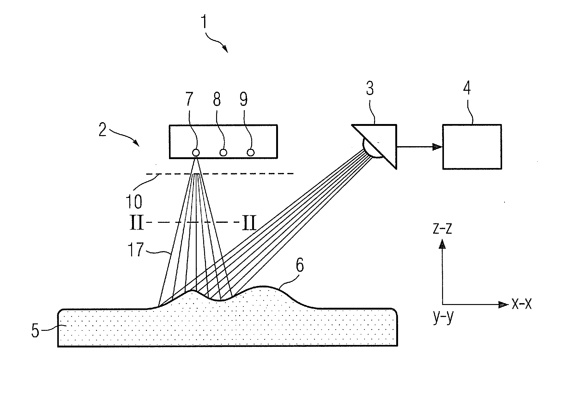
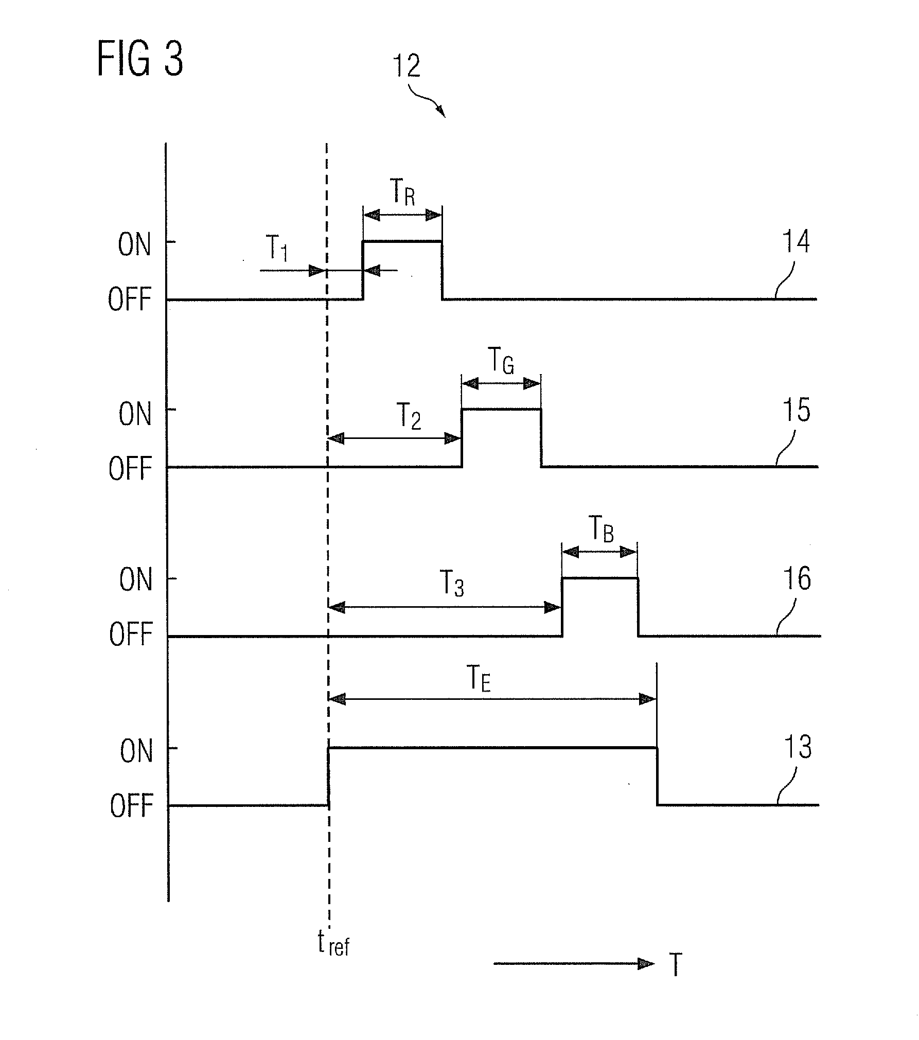
[0008]In one embodiment, said light projection means comprises at least two light sources of different colours selected from red, green and blue, said light projection means further including means for strobing said light sources for said distinct time intervals. Using light of two or more primary colours such as red, green and blue results in formation of distinct colour planes in the image, which is exposed in the entire duration of said distinct intervals of strobing. This helps in accurately capturing the motion of the object during the exposure time.

Problems solved by technology

However, such techniques are typically suitable for measuring two-dimensional motion and hence cannot be conveniently used for measuring three-dimensional motion such as spatial modes of vibration, which are important for damage and impact analysis of machine parts and civil structures.
However, these systems are limited by the frame rate of the camera used, which is a function of the time interval between the capture of two successive image frames.
The cost of cameras increases as the frame rates increases, thereby inducing a practical limit on the frame rate.
This poses a difficulty in capturing high speed motion by such systems as they have a maximum and minimum limitation of speed for a moving object.

Method used


Image

  • Measurement of three-dimensional motion characteristics
  • Measurement of three-dimensional motion characteristics
  • Measurement of three-dimensional motion characteristics

Examples


Embodiment Construction

[0024]Embodiments of the present invention described in detail herein provide a system and method for measurement of three-dimensional (3D) motion of an object that may be used for higher speed motion measurements using image acquisition means, such as a camera, having relatively lower frame rates. To that end, high speed images of an object are acquired by projecting light of multiple different colours for distinct time intervals on the object and capturing an image of the object with an exposure time, such that the duration of the exposure time is inclusive of the distinct time intervals of projection light of different colours. The above technique is referred to herein as colour plane slicing. Using this technique of colour plane slicing, it is possible for low frame rate (hence, low cost) colour camera to get multiple images of respective colours at very small intervals superimposed on a single image captured during the exposure time. Further, to measure motion in 3D, the 3D sha...


PUM


Abstract

A system for measurement of three-dimensional motion of an object is provided. The system includes a light projection means adapted for projecting, for distinct time intervals, light of at least two different colors with a cross-sectional pattern of fringe lines onto a surface of the object and also includes image acquisition means for capturing an image of the object during an exposure time, wherein the distinct time intervals are within the duration of the exposure time. The system further includes image processing means adapted for processing the image to obtain a different depth map for each color based on a projected pattern of fringe lines on the object as viewed from the position of the image acquisition means, to determine corresponding points on the depth maps of each color, and to determine a three-dimensional motion characteristic of the object based on the positions of corresponding points on the depth maps.

Description

CROSS REFERENCE TO RELATED APPLICATIONS[0001]This application claims priority of European Patent Office application No. 10003832.2 EP filed Apr. 9, 2010, which is incorporated by reference herein in its entirety.FIELD OF INVENTION[0002]The present invention relates to characterization of three-dimensional motion of an object.BACKGROUND OF INVENTION[0003]Dynamic measurement of motion of a moving object, for example, a vibrating object, is conventionally done using camera based systems that capture successive images of the moving object at successive intervals of time, whereby a motion characteristic is determined based on the position of the object in successively captured image frames. Other known techniques for measurement of vibration motion include the use of strain gages and laser Doppler based methods. However, such techniques are typically suitable for measuring two-dimensional motion and hence cannot be conveniently used for measuring three-dimensional motion such as spatial ...

Claims


Application Information

Patent Timeline
Patent Type & Authority Applications(United States)
IPC IPC(8): G06K9/00
CPCG01H9/002G01B11/2509
Inventor VENKATESAN, VARUN AKURBAGARIA, VENKATESH
Owner SIEMENS AG
Learn More