
Compact holograhic human-machine interface

Inactive Publication Date: 2011-10-13
HOLOTOUCH
View PDF0 Cites 59 Cited by
  • Summary
  • Abstract
  • Description
  • Claims
  • Application Information

AI Technical Summary

Benefits of technology

Recording holograms in emulsion affixed to glass or acrylic plate produces copies of holograms that are essentially “one off”. Moreover, recording holograms in emulsion generally offers both inconsistent images and high per unit cost. By contrast, surface relief holograms, which are essentially ridges in the surface of materials, such as polycarbonate, offer the possibility of large volumes of identical copies and very low per unit copy cost. An example of such surface relief holograms are those used in credit cards and driver's licenses, which are actually recorded as transmission holograms.
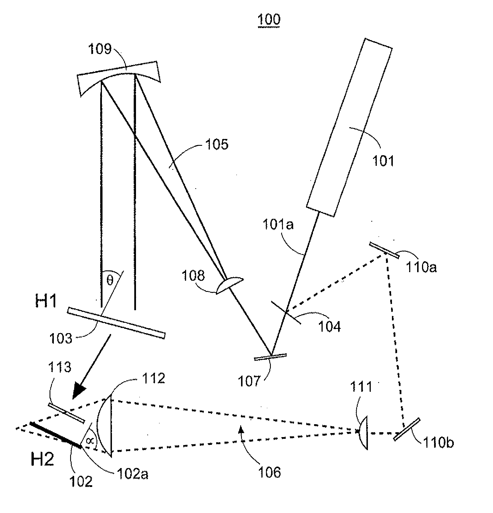
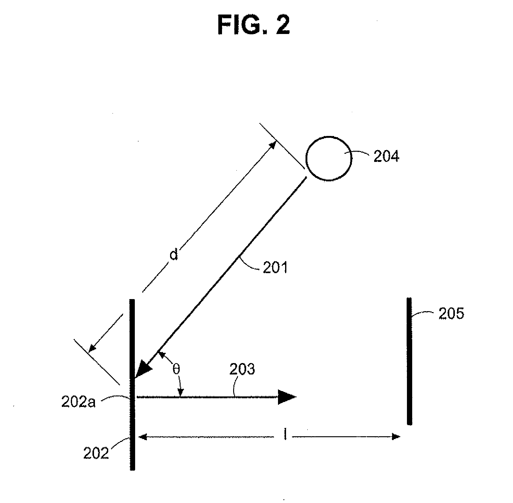
As will be discussed in greater detail below, to address some of the foregoing concerns a method and system are provided that, in at least one embodiment, mitigate the potential curvature of a reproducing light path d and the distortion of holographic images caused thereby while reducing the reproducing light path such that a reproducing light source can be positioned closer to the medium bearing the hologram as compared to conventional arrangements.
Potential curvature of the reproducing light path is avoided by converging or bending together of the wave front of the reference beam through use of a lens that is configured to form curved fringes on the second holographic recording medium such that those fringes are recorded in reverse or conjugate geometry with respect to a diverging or spreading reproducing light source.
In order to provide a highly compact holographic recording and reproduction system of the present invention with a very wide angle of reconstruction (i.e., greater than 45 degrees), the reconstructing light source can be positioned as close as possible to the plate or film to which the hologram is affixed. In particular in accordance with embodiments of the invention, angles of reconstruction greater than 80 degrees are possible.
Reduced cost and ease of integration of holograms with features of a controlled device can be facilitated through various embodiments of the present invention. Also, the design, manufacture, and engineering of touchless human machine interfaces (HMIs) for electronic and electro-mechanical devices can also be facilitated through various embodiments of the present invention. The present invention is also more efficacious when recording master holograms and minimizes image distortion caused by vibrations or air currents occurring during hologram recording process.
Media to which a hologram may be affixed or which otherwise bear a hologram according to the present invention can be very thin, as compared with more cumbersome and thicker edge-lit holograms taught by the prior art. Depending upon durability concerns related to operation of holographic HMIs and refractive qualities of materials to which holograms may be affixed, those materials may include one of one-quarter inch or greater acrylic plate or glass or other transparent or translucent media. Thinner materials to which holograms may be affixed permit holographic HMIs, for example, to be more compact and lighter than conventional holographic HMIs. Holograms recorded in accordance with the various aspects of the present invention can be reproduced by compact, inexpensive and long-lasting light sources such as LEDs, striking media to which holograms are affixed at large angles of reconstruction, positioned close to media, thereby permitting reduced size and weight of touchless, holographic HMIs. The methods and systems described herein also facilitate creation of colorful holographic images, an essential component of commercial viability of touchless, holographic HMIs.

Problems solved by technology

Moreover, recording holograms in emulsion generally offers both inconsistent images and high per unit cost.

Method used


Image

  • Compact holograhic human-machine interface
  • Compact holograhic human-machine interface
  • Compact holograhic human-machine interface

Examples


Embodiment Construction

According to an aspect of the present invention, a method and system are provided where a holographic image is reconstructed substantially perpendicular to a surface of a medium, such as a plate or film, to which a hologram is affixed while being illuminated by a reproducing light source positioned at an acute or scant angle, for example, of about 12.5 degrees, and less than 45 degrees, with respect to the plane of the medium to which the hologram is affixed, which corresponds to an angle of reconstruction of about 77.5 degrees. In addition, the reproducing light source is positioned very close to the medium to which the hologram is affixed, as compared to conventional hologram reconstruction. In a preferred embodiment, the reproducing light source is positioned about one inch from the center of the medium to which the hologram is affixed.

A holographic image of a hologram recorded in accordance with the present invention is reconstructed when light illuminates the medium to which th...


PUM


Abstract

A method of recording an object image of a first hologram as a second hologram is provided. A first hologram is recorded at a first angle of reconstruction and a holographic recording medium is provided. An object beam is directed through the first hologram at the first angle of reconstruction to reconstruct the object image on the recording medium. The recording medium is struck with a reference beam at a second angle of reconstruction to form a wave interference pattern with the object beam. The second angle of reconstruction is between 45 and 90 degrees. The wave interference pattern is recorded. A switch is provided that includes a hologram that has an angle of reconstruction between 45 and 90 degrees. A reproducing light source is positioned to direct light through the hologram at the angle of reconstruction to form a holographic image at a predetermined distance from the hologram. The switch includes a detector that detects the presence of an object proximate to the holographic image. The axis of the detector beam source is not perpendicular to the plane of the medium to which its hologram is affixed.

Description

BACKGROUND OF THE INVENTION1. Field of the InventionThe present invention relates to a method and system for creating a holographic image that can be reconstructed by a light source positioned in close proximity to a medium bearing a hologram at an acute angle relative to the plane of the medium, and in particular to angles less than 45 degrees. At least one embodiment of a method and system in accordance with the disclosure are described with reference to the various figures included herein.2. Description of Related ArtPhoto-sensitive media are conventionally used to record a holographic image, such as a letter, a picture, or a symbol. Alternative photo-sensitive media include, but are not limited to, photo-sensitive film and transparent or translucent sheets or plate composed of acrylic or glass and coated with a high-contrast, high-resolution, photo-sensitive emulsion. In addition, holograms can be recorded using surface relief hologram production procedures and techniques.Recons...

Claims


Application Information

Patent Timeline
IPC IPC(8): G03H1/20G03H1/22
CPCG03H1/0244G03H1/20G03H1/22G03H1/2286G03H2001/0413G03H2001/0473G03H2210/20G03H2222/12G03H2222/42G03H2222/54G03H2227/06G03H1/2249G03H2001/226G03H2001/2223
Inventor MCPHETERS, R. DOUGLASCIAUDELLI, JOSEPHCVETKOVICH, THOMAS J.
Owner HOLOTOUCH
Learn More