Eureka AIR delivers breakthrough ideas for toughest innovation challenges, trusted by R&D personnel around the world.

Isolator

a technology of isolation device and belt, which is applied in the direction of mechanical equipment, couplings, hoisting equipment, etc., can solve the problems of reducing the life of the belt, and the inability of the belt tensioner to accommodate all the variable torque characteristics

Active Publication Date: 2011-10-06
THE GATES CORP
View PDF12 Cites 64 Cited by
  • Summary
  • Abstract
  • Description
  • Claims
  • Application Information

AI Technical Summary

Benefits of technology

[0009]The invention comprises an isolator comprising a shaft, a pulley journalled to the shaft on a first bushing and a second bushing, the shaft comprising a shaft stop disposed on a shaft radially outer surface, the pulley and the shaft rotationally moveable relative to each other, the pulley comprising an inner hub, the inner hub having a pulley stop disposed to cooperatively engage the shaft stop, a torsion spring engaged with the shaft and the pulley, the torsion spring exerting a contractive force parallel to an axis of rotation in order to retain the pulley on the shaft, a cover member fixed to the shaft, the pulley urged into engagement with the cover member by the torsion spring axial contractive force, and a rubber member disposed on the shaft stop for engaging the pulley stop.

Problems solved by technology

A belt tensioner cannot accommodate all of the variable torque characteristics.
The result can be noise and decreased belt life due to instantaneous belt slippage.

Method used


Image

  • Isolator
  • Isolator
  • Isolator

Examples


Embodiment Construction

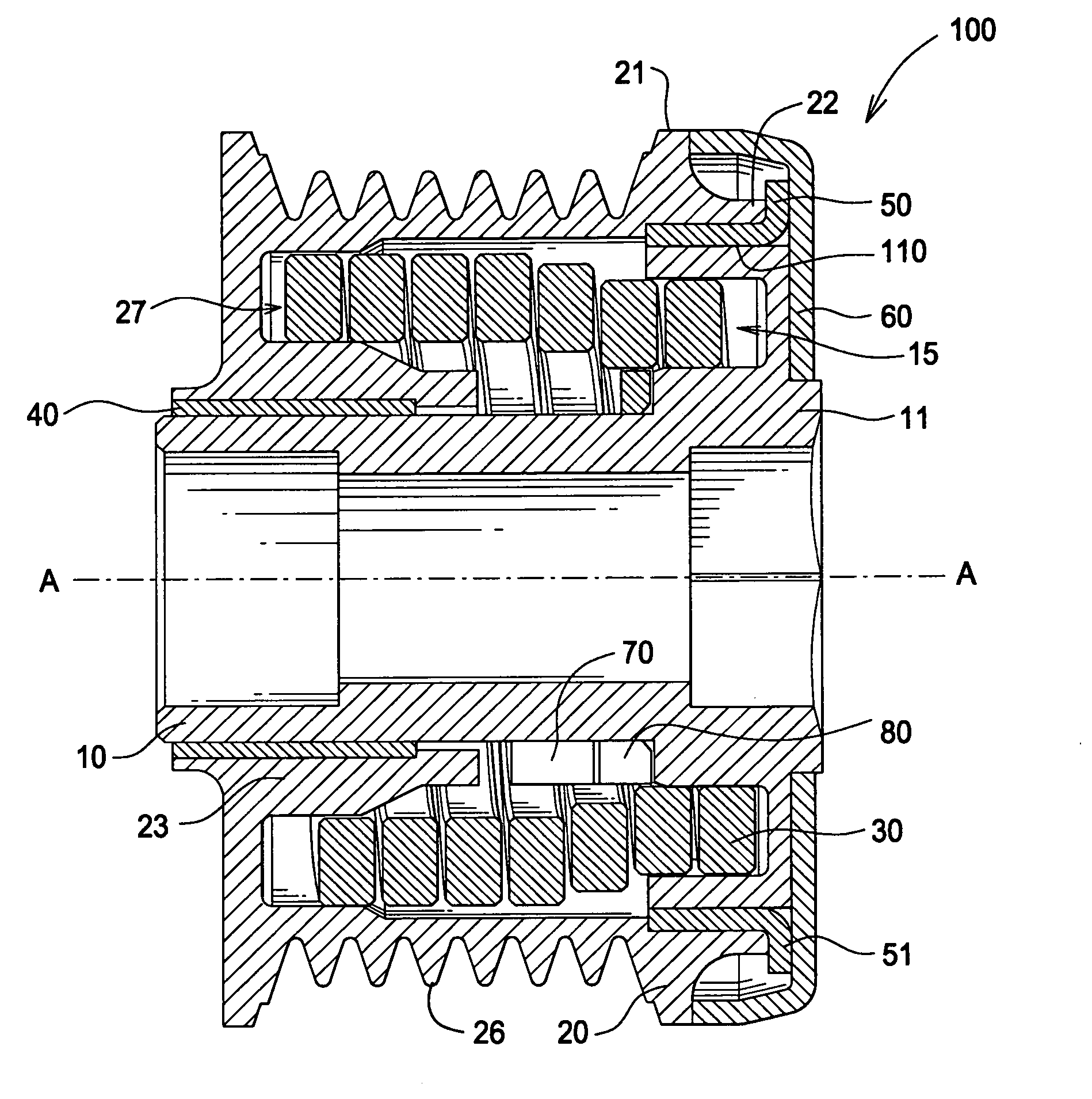
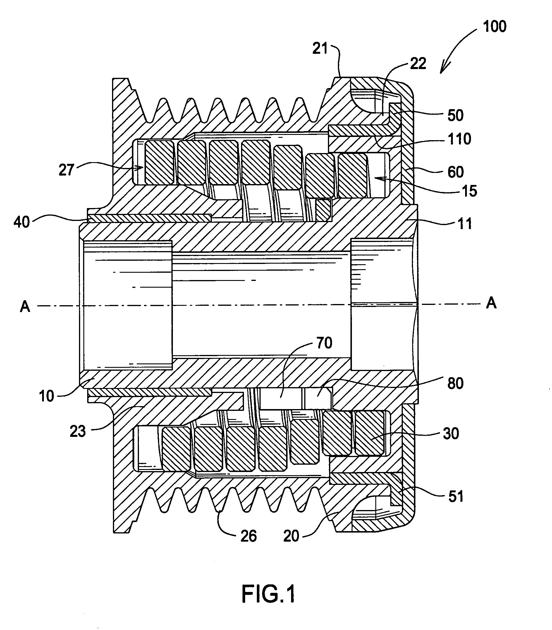
[0017]FIG. 1 is a cross sectional view of the inventive isolator. Isolator 100 comprises a shaft 10 and pulley 20. Pulley 20 is journalled to shaft 10 on bushing 40 and bushing 50. Pulley 20 is connected to shaft 10 by a torsion spring 30.

[0018]Torsion spring 30 is an extension type spring with a minimum coil spacing in the no load state. In the no load state spacing between each coil can be anywhere between 0 mm (in contact) up to approximately 0.5 mm. During assembly one end of the torsion spring is pressed into a receiving portion 27 of pulley 20 and the other end is pressed into a receiving portion 15 of shaft 10. Once the torsion spring is installed, the shaft and pulley are pulled apart by approximately 2 mm to 3 mm, whereby the torsion spring is elongated to a desired axial length in order to achieve the intended axial contractive force of approximately 20N to 50 N. The contractive torsion spring rate is in the range of approximately 5N / mm to 20 N / mm. The axial contractive sp...


PUM


Abstract

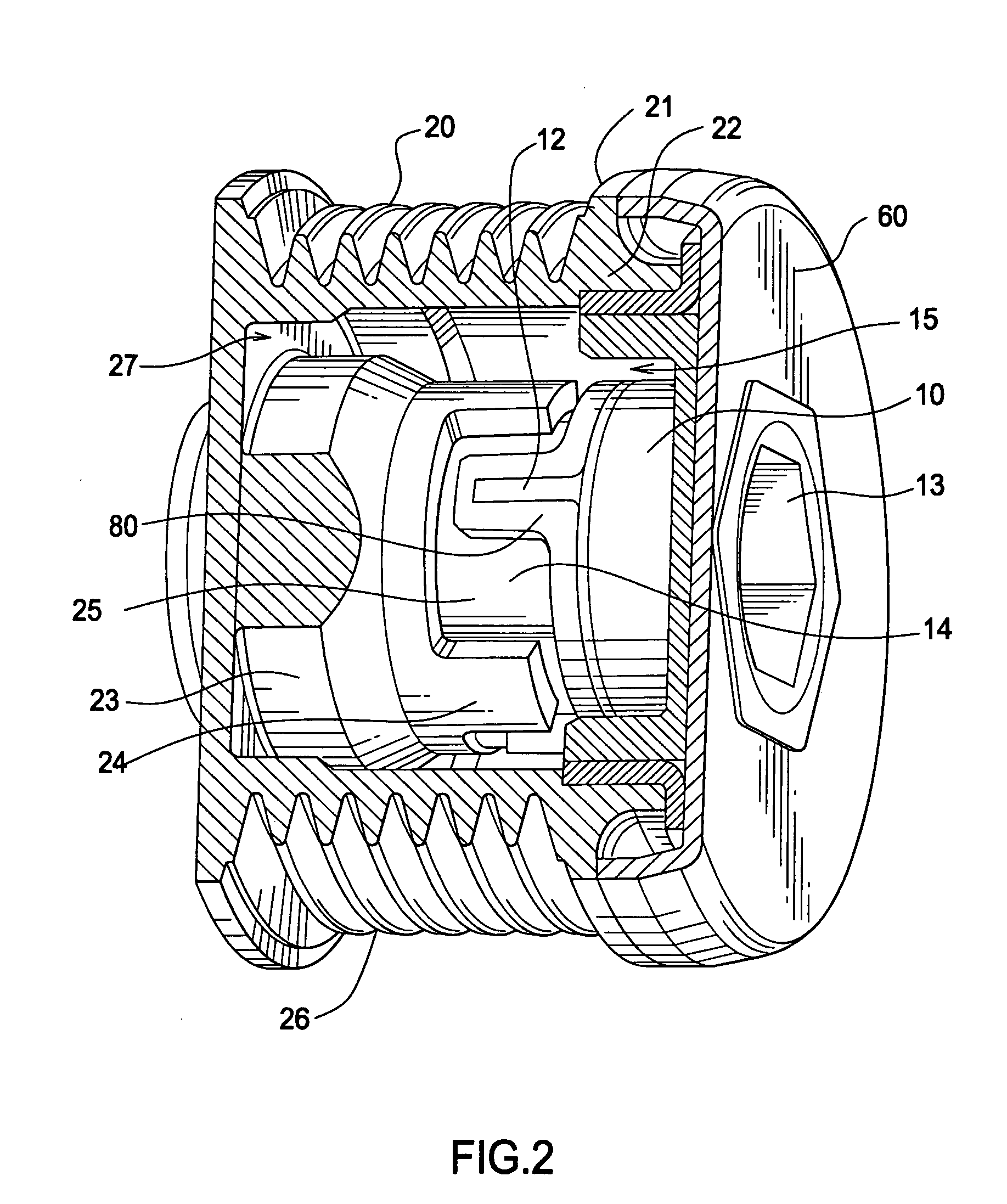
An isolator comprising a shaft (10), a pulley (20) journalled to the shaft on a first bushing (40) and a second bushing (50), the shaft comprising a shaft stop (12) disposed on a shaft radially outer surface (14), the pulley and the shaft rotationally moveable relative to each other, the pulley comprising an inner hub (23), the inner hub having a pulley stop (24) disposed to cooperatively engage the shaft stop, a torsion spring (30) engaged with the shaft and the pulley, the torsion spring exerting a contractive force parallel to an axis of rotation (A-A) in order to retain the pulley on the shaft, a cover member (60) fixed to the shaft, the pulley urged into engagement with the cover member by the torsion spring axial contractive force, and a rubber member (80) disposed on the shaft stop for engaging the pulley stop.

Description

FIELD OF THE INVENTION[0001]The invention relates to an isolator, and more particularly to an alternator isolator having a torsion spring exerting an axial contractive force to retain the pulley on the shaft.BACKGROUND OF THE INVENTION[0002]Vehicle internal combustion engines typically comprise a front end belt driven accessory drive. The accessories can include power steering, an alternator, water pump and so on. The accessory drive can also be referred to as a serpentine drive since the belt often traces a circuitous path about the front plane of an engine.[0003]A typical serpentine drive system includes a driving pulley on the crankshaft of an internal combustion engine of the vehicle, a series of driven pulleys for the accessories and a poly-V belt trained about the driving and driven pulleys. An advantage of the serpentine drive is that by providing an automatic belt tensioner on the belt the accessories can be fixedly mounted.[0004]Particularly where the engine is of the four-...

Claims


Application Information

Patent Timeline
IPC IPC(8): F16H55/36
CPCF16F15/1216F16H2055/366F16H55/36F16F15/1217F16D41/206F16F15/121
Inventor SERKH, ALEXANDERWARD, PETERALI, IMTIAZSCHNEIDER, DEAN
Owner THE GATES CORP
Why Eureka
Eureka Blog
Learn More