
Fixing device and image forming apparatus incorporating same

a technology of fixing device and image forming apparatus, which is applied in the direction of ohmic resistance heating, electrographic process apparatus, instruments, etc., can solve the problems of faulty fixing of toner image on recording medium, faulty fixing of fixing belt, and reducing heat transmission efficiency of transmitting heat from the resistant heat generator to the fixing bel

Active Publication Date: 2011-09-22
RICOH KK
View PDF99 Cites 98 Cited by
  • Summary
  • Abstract
  • Description
  • Claims
  • Application Information

AI Technical Summary

Benefits of technology

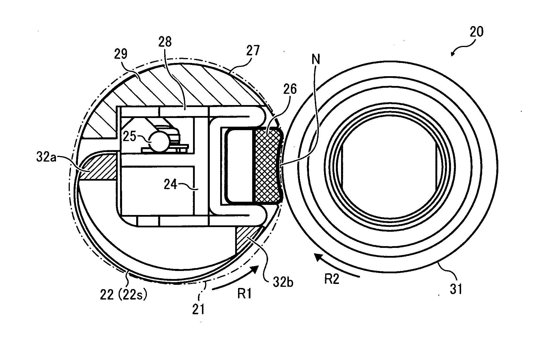
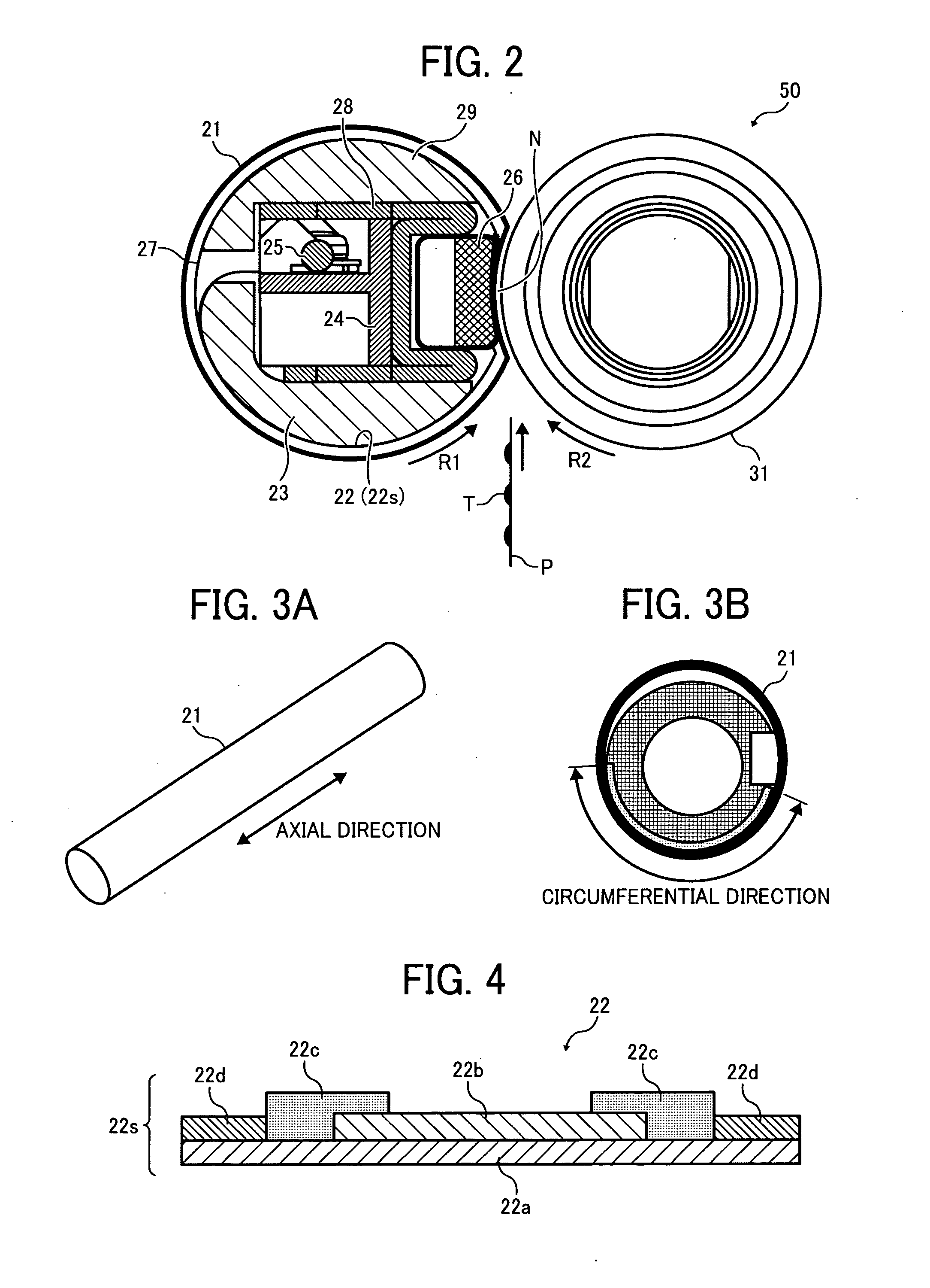
[0006]The fixing device used in such image forming apparatuses may include a flexible, endless fixing belt formed into a loop and a resistant heat generator provided inside the loop formed by the fixing belt to heat the fixing belt, to shorten a warm-up time or a time to first print (hereinafter also “first print time”). Specifically, the resistant heat generator faces the inner circumferential surface of the fixing belt across a slight gap through which radiation heat generated by the resistant heat generator is transmitted to the fixing belt. A pressing roller presses against a nip formation member also provided inside the loop formed by the fixing belt via the fixing belt to form a nip between the fixing belt and the pressing roller through which the recording medium bearing the toner image passes. As the recording medium bearing the toner image passes through the nip, the fixing belt heated by radiation heat generated by the resistant heat generator and the pressing roller together apply heat and pressure to the recording medium to fix the toner image on the recording medium.

Problems solved by technology

However, the above-described fixing device including the resistant heat generator and the fixing belt has a drawback in that rotation and vibration of the pressing roller repeatedly applies mechanical stress to the resistant heat generator via the fixing belt, which bends the resistant heat generator.
The repeated bending of the metal resistant heat generator causes fatigue failure and concomitant breakage or disconnection of the wiring of the resistant heat generator, resulting in faulty heating of the fixing belt.
Moreover, the slight gap provided between the resistant heat generator and the fixing belt to prevent the resistant heat generator from pressing against the fixing belt may increase heat resistance between the resistant heat generator and the fixing belt and therefore decrease heat transmission efficiency of transmitting heat from the resistant heat generator to the fixing belt.
Also, the mechanical stress applied by the pressing roller may cause a part of the resistant heat generator to contact the fixing belt while other parts of the resistant heat generator are isolated from the fixing belt, disturbing uniform heat transmission from the resistant heat generator to the fixing belt throughout the axial direction of the fixing belt and thus resulting in faulty fixing of the toner image on the recording medium.

Method used


Image

  • Fixing device and image forming apparatus incorporating same
  • Fixing device and image forming apparatus incorporating same
  • Fixing device and image forming apparatus incorporating same

Examples


Embodiment Construction

[0032]It will be understood that if an element or layer is referred to as being “on”, “against”, “connected to”, or “coupled to” another element or layer, then it can be directly on, against, connected or coupled to the other element or layer, or intervening elements or layers may be present. In contrast, if an element is referred to as being “directly on”, “directly connected to”, or “directly coupled to” another element or layer, then there are no intervening elements or layers present. Like numbers refer to like elements throughout. As used herein, the term “and / or” includes any and all combinations of one or more of the associated listed items.

[0033]Spatially relative terms, such as “beneath”, “below”, “lower”, “above”, “upper”, and the like, may be used herein for ease of description to describe one element or feature's relationship to another element(s) or feature(s) as illustrated in the figures. It will be understood that the spatially relative terms are intended to encompas...


PUM


Abstract

A fixing device includes an endless belt-shaped fixing member formed into a loop and rotatable in a predetermined direction of rotation, a pressing member contacting an outer circumferential surface of the fixing member, a heater support assembly provided inside the loop formed by the fixing member, and a laminated heater supported by the heater support assembly and provided inside the loop formed by the fixing member. The laminated heater includes an elastic sheet contacting an inner circumferential surface of the fixing member with pressure generated by elasticity of bending of the elastic sheet to heat the fixing member.

Description

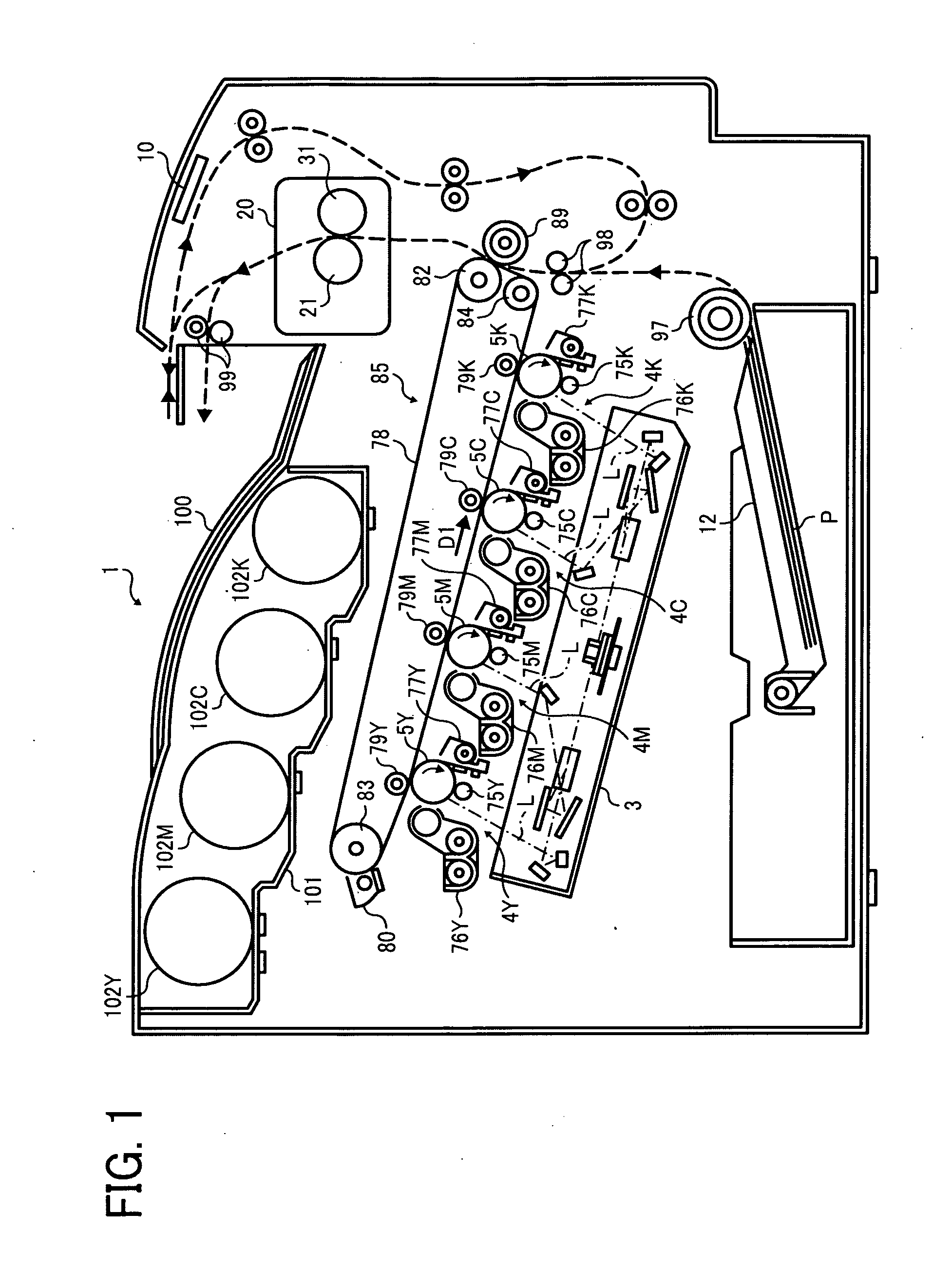
PRIORITY STATEMENT[0001]The present patent application claims priority from Japanese Patent Application No. 2010-061897, filed on Mar. 18, 2010 in the Japan Patent Office, which is hereby incorporated herein by reference in its entirety.BACKGROUND OF THE INVENTION[0002]1. Field of the Invention[0003]Example embodiments generally relate to a fixing device and an image forming apparatus, and more particularly, to a fixing device for fixing a toner image on a recording medium and an image forming apparatus including the fixing device.[0004]2. Description of the Related Art[0005]Related-art image forming apparatuses, such as copiers, facsimile machines, printers, or multifunction printers having at least one of copying, printing, scanning, and facsimile functions, typically form an image on a recording medium according to image data. Thus, for example, a charger uniformly charges a surface of an image carrier; an optical writer emits a light beam onto the charged surface of the image ca...

Claims


Application Information

Patent Timeline
IPC IPC(8): G03G15/20
CPCG03G2215/2035G03G15/2039G03G2215/2041
Inventor ISHII, KENJIYOSHIKAWA, MASAAKIYAMAGUCHI, YOSHIKISHIMOKAWA, TOSHIHIKOIWAYA, NAOKIIMADA, TAKAHIROIKEBUCHI, YUTAKATOKUDA, TETSUOHASE, TAKAMASASESHITA, TAKUYAYOSHINAGA, HIROSHIFUJIMOTO, IPPEI
Owner RICOH KK
Learn More