
Spectacle lens with color-neutral Anti-reflection coating and method of making the same

Active Publication Date: 2011-09-22
CARL ZEISS VISION INT GMBH
View PDF9 Cites 15 Cited by
  • Summary
  • Abstract
  • Description
  • Claims
  • Application Information

AI Technical Summary

Benefits of technology

[0021]An object of the present invention is to minimize the difference of the color of the residual reflectance of the antireflection coating under different lighting in order to achieve the same appearance of the reflectance color regardless of the environment and lighting conditions. Accordingly, the spectacle lens according to the invention is provided with an antireflection coating which has a color-neutrally appearing residual reflectance not only under a natural daylight spectrum but also under lighting conditions with an illumination spectrum which differs from a natural daylight spectrum. In particular, this is also ensured for spectacle lenses which are provided with antireflection coating and a scratch-resistant layer, whose refractive index differs from the refractive index of the spectacle lens substrate. The object is achieved when the fact that the color-neutral / white appearance of the residual reflectance is to be ensured under different lighting conditions is taken into account when configuring the interference layer system of which the antireflection coating is constructed.
[0026]The antireflection coating of the spectacle lens can, for example, include an interference layer system with a layer stack of alternating high and low refractive materials. The materials used, of which the layers are formed, are transparent in the visual spectral region. The layer thicknesses of the individual layers are generally smaller than the wavelength of the visible light. It can, for example, be a layer system of three different layer materials. The layer closest to the substrate is, for example, of a material having a refractive index which is as low as possible. The next layer is of a material having a refractive index which is as high as possible, and the material of the third layer has a refractive index which has a value between that of the two other materials. For example, the interference layer system can have the following layer sequence (sequence starting from the substrate): 22 nm HfO2, 14 nm SiO2, 36 nm HfO2, 88 nm Nb2O5, 24 nm HfO2, 75 nm SiO2. Thereby, the layer material SiO2 has the lowest refractive index, the material Nb2O5 the highest refractive index, and the material HfO2 the intermediate refractive index. Further, it can be advantageous to apply a further layer on the outer layer which changes the surface characteristics of the antireflection layer system so that the spectacle lens is especially easy to clean. If this is the case, the individual layer thicknesses need to be considered during configuration. Such easy-to-clean coatings are hydrophobic and / or oleophobic coatings having a surface energy under 20 mN / m.

Problems solved by technology

The light reflected by the spectacle lens causes disturbing glare on its front side as well as its back side facing the wearer of the spectacles.
The reflections on the front side of the spectacle lens are perceived as disturbing by a person standing opposite the wearer of the spectacles.
The light reflected by the back side causes the person wearing the spectacles to perceive, among other unwanted optical effects, a blurred image.
Because of the finite number of layers in an antireflection coating, it is not possible to completely eliminate the reflection over the entire visible spectrum.
Therefore, antireflection coatings generally lead to a colored residual reflection.
Even though the antireflection coating described in United States patent application publication 2007 / 0202251 A1 has essentially proven effective also for plastic spectacle lenses with scratch-resistant coating and antireflection coating, it has been found that while the residual reflection is not consciously perceived in natural sunlight it is perceived to be disturbing, for example, for both the wearer of the spectacles and the person standing opposite the wearer of the spectacles in rooms with fluorescent tube lighting.

Method used


Image

  • Spectacle lens with color-neutral Anti-reflection coating and method of making the same
  • Spectacle lens with color-neutral Anti-reflection coating and method of making the same
  • Spectacle lens with color-neutral Anti-reflection coating and method of making the same

Examples


Embodiment Construction

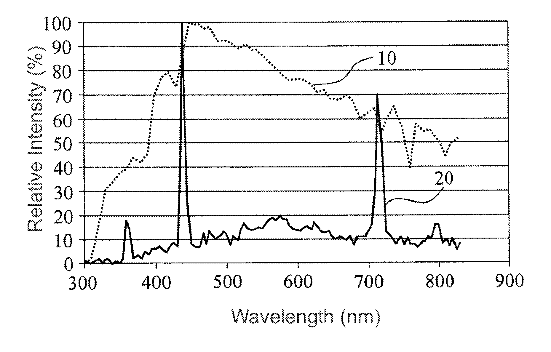
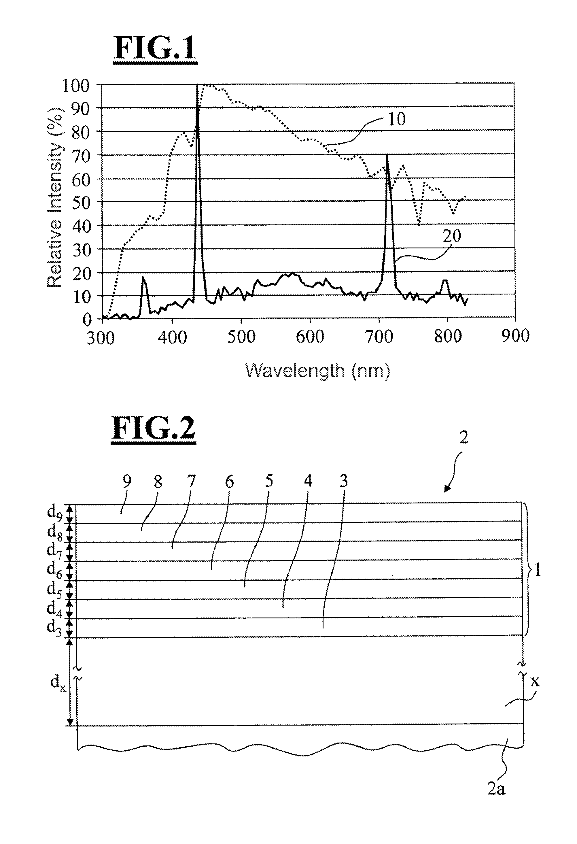
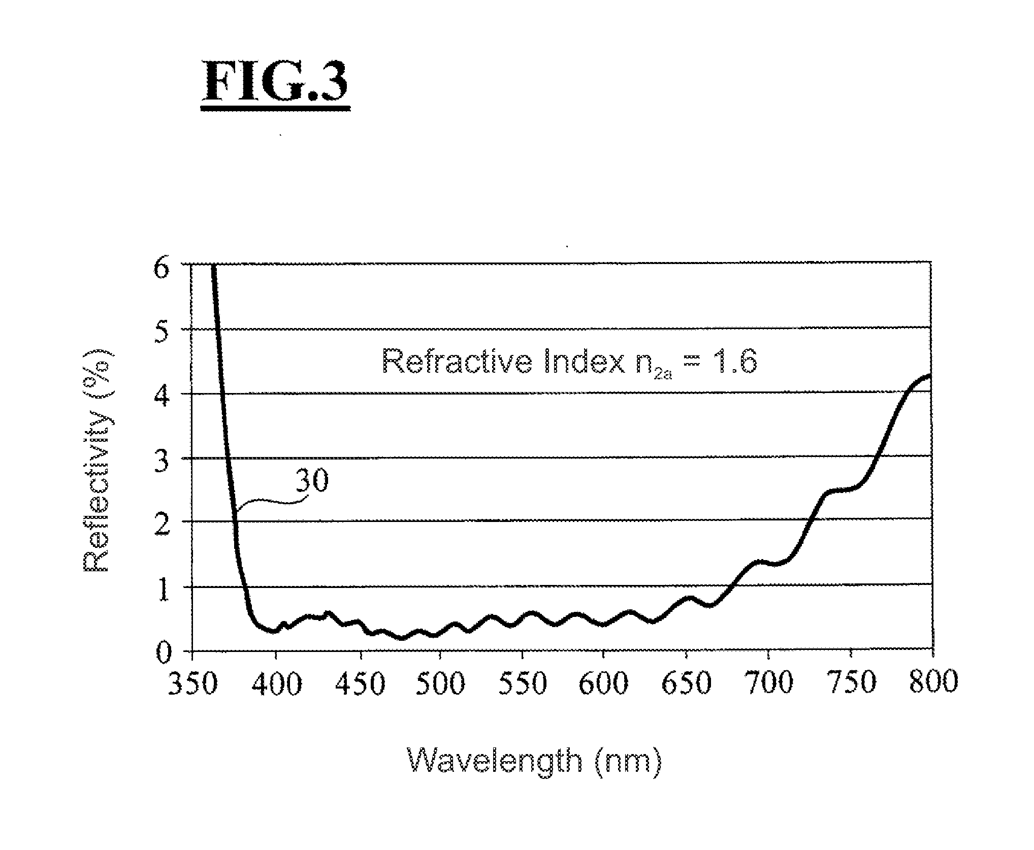
[0038]FIG. 1 shows the illumination curves of daylight 10 standardized to 100% intensity (here approximated to the D65 standard known to the person of ordinary skill in the art) and a fluorescent tube 20. When simultaneously considering both illuminations (10, 20) during the configuration of the interference layer system, one obtains the spectral reflectance curve 30 of FIG. 3 for the antireflection coating 1 of a spectacle lens 2 shown in FIG. 2 (not to scale).

[0039]The antireflection coating 1 in the shown embodiment includes a scratch-resistant layer (x) and seven individual layers (3, 4, 5, 6, 7, 8, 9) which form the interference optical system.

[0040]The spectacle lens 2a which forms the substrate and has a refractive index n2a of 1.6 is initially provided with a scratch-resistant layer (x). The scratch-resistant layer (x) has a refractive index nx of 1.6 and a thickness dx of 2.5 μm. The system of the antireflection coating 1, which functions as an interference optical layer sy...


PUM

PropertyMeasurementUnit
Thicknessaaaaaaaaaa
Thicknessaaaaaaaaaa
Surface energyaaaaaaaaaa

Abstract

A spectacle lens (2) has an antireflective coating (1). The antireflective coating (1) produces a residual reflection appearing color-neutral not only under illumination with a natural daylight spectrum, but also under an illumination with an illumination spectrum deviating from the natural daylight spectrum. A method for making a spectacle lens (2) having an antireflective coating (1) is described in which an optical lens (2a) is provided and a layer sequence of layers (3, 4, 5, 6, 7, 8, 9) with alternately high and low refractive material forming the antireflective coating (1) is applied to the optical lens. The antireflective coating (1) is applied with the proviso that the antireflective coating (1) produces a residual reflection appearing color-neutral not only under illumination with a natural daylight spectrum, but also under an illumination with an illumination spectrum deviating from the natural daylight spectrum.

Description

CROSS REFERENCE TO RELATED APPLICATIONS[0001]This application is a continuation application of international patent application PCT / EP 2009 / 006035, filed Aug. 20, 2009, designating the United States and claiming priority from German application 10 2008 041 869.2, filed Sep. 8, 2008, and the entire content of both applications is incorporated herein by reference.FIELD OF THE INVENTION[0002]The invention relates to a spectacle lens having an anti-reflection coating as well as a method for making an anti-reflection coating for a spectacle lens.BACKGROUND OF THE INVENTION[0003]Incident light is reflected on the surfaces of a spectacle lens. The proportion of the reflected light is dependent on the incident angle and the refractive index of the lens. Thus, for example, the proportion of light reflected on each surface of an untreated spectacle lens having a refractive index of 1.5 with perpendicular incident light is about 4%, so that only about 92% of the incoming light is transmitted t...

Claims


Application Information

Patent Timeline
IPC IPC(8): G02C7/02
CPCG02B1/115B29D11/00923
Inventor VON BLANCKENHAGEN, BERNHARD
Owner CARL ZEISS VISION INT GMBH
Learn More