Bistable display device

a display device and bistable technology, applied in the field can solve the problems of poor image display on the electronic device, reduced reflectivity, non-excellent touch sensing, etc., and achieve the effects of reducing human error in assembly, improving flexibility and thinness of bistable display devices, and reducing assembly process and cos

Active Publication Date: 2011-09-22
E INK HLDG INC
View PDF9 Cites 12 Cited by
  • Summary
  • Abstract
  • Description
  • Claims
  • Application Information

AI Technical Summary

Benefits of technology

[0006]The present invention relates to a bistable display device, which can improve the flexibility and thinness of the bistable display device and reduce the human error in assembling so as to reduce the assembling process and cost.

Problems solved by technology

However, if the capacitive touch or the resistive touch is applied to a reflective-type bistable display device, the sensing module disposed on the display module will reduce the reflectivity and thus images displayed on the electronic device are poor.
However, since the assembling process is performed by assemblers, it often causes some problems such as non-excellent touch sensing result or improper assembling and so on resulting from the mistaken operation of the assemblers when assembling the electromagnetic sensing module and the display module together.

Method used


Image

  • Bistable display device
  • Bistable display device
  • Bistable display device

Examples


Embodiment Construction

[0016]It is to be understood that other embodiment may be utilized and structural changes may be made without departing from the scope of the present invention. Also, it is to be understood that the phraseology and terminology used herein are for the purpose of description and should not be regarded as limiting. The use of “including,”“comprising,” or “having” and variations thereof herein is meant to encompass the items listed thereafter and equivalents thereof as well as additional items. Unless limited otherwise, the terms “connected,”“coupled,” and “mounted,” and variations thereof herein are used broadly and encompass direct and indirect connections, couplings, and mountings. Accordingly, the descriptions will be regarded as illustrative in nature and not as restrictive.

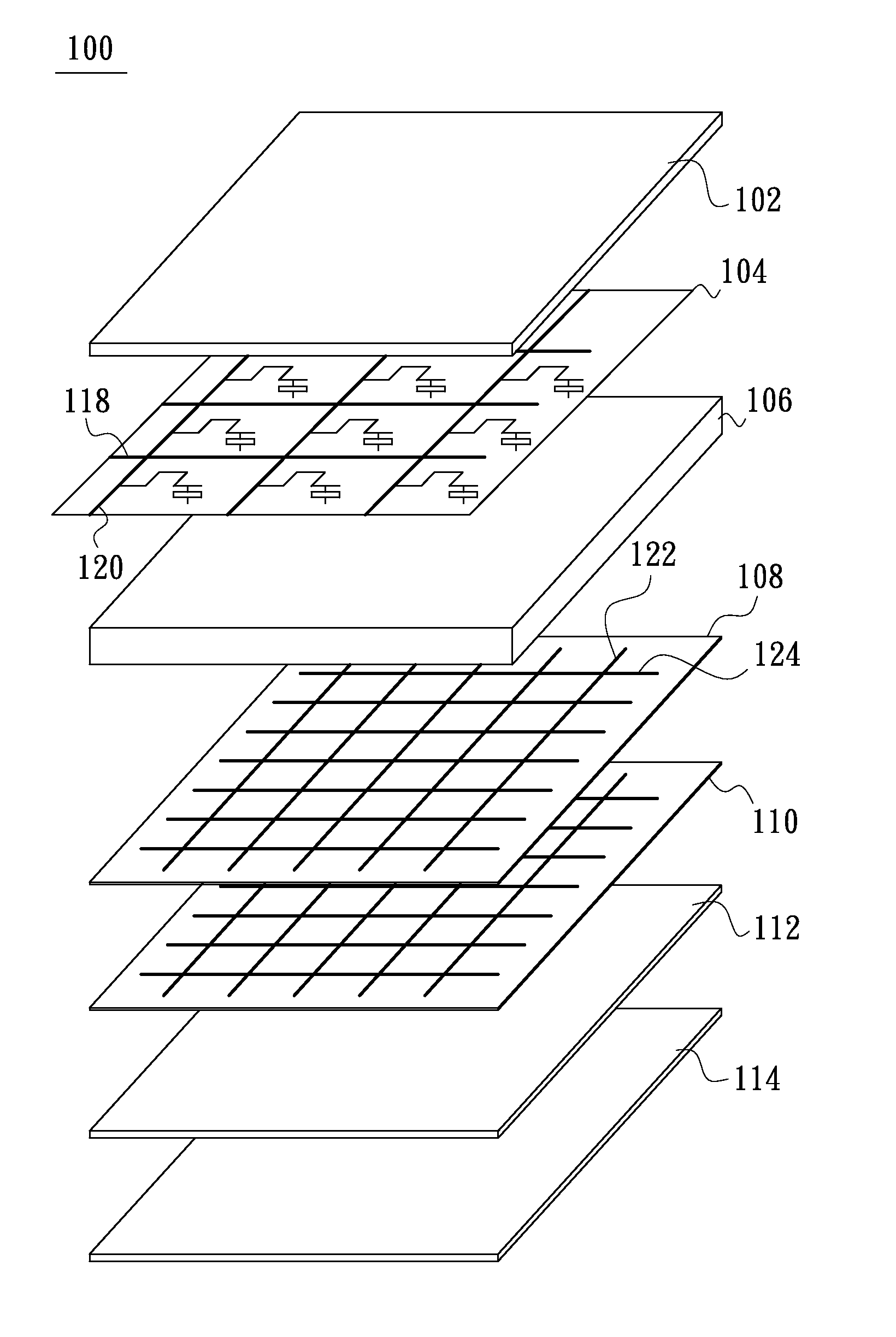
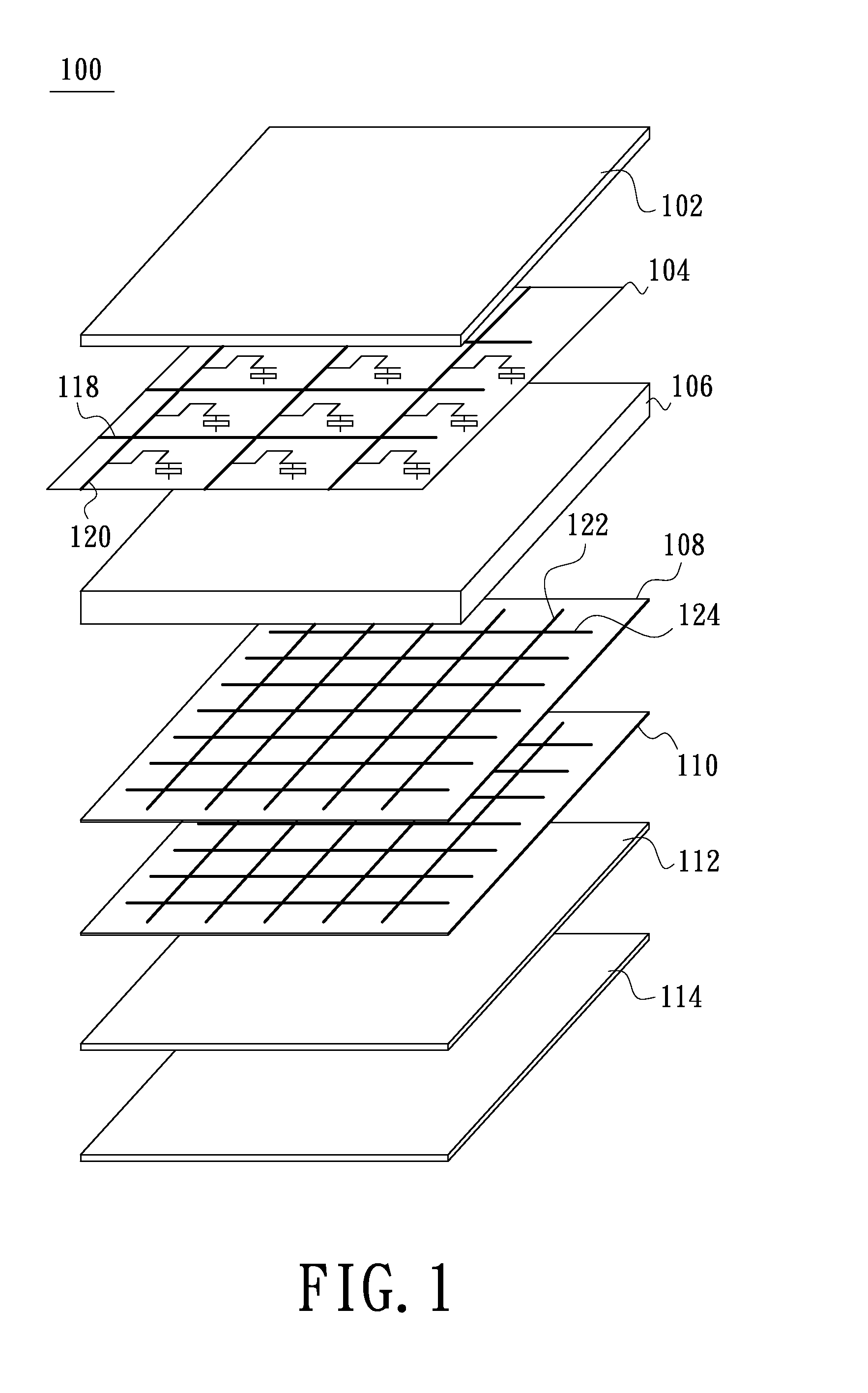
[0017]Refer to FIG. 1, which is a schematic perspective exploded view of a bistable display device in accordance with an exemplary embodiment of the present invention. The bistable display device 100 comprises a...


PUM


Abstract

A bistable display device comprises a substrate, a display film, a display circuit, an electromagnetic sensing layer, a shielding layer and a protection layer. The substrate has an upper surface and a lower surface. The display film is disposed on the upper surface of the substrate. The display circuit is formed on the upper surface of the substrate. The electromagnetic sensing layer is formed on the lower surface of the substrate. The shielding layer is disposed under the electromagnetic sensing layer. The protecting layer is disposed under the shielding layer.

Description

BACKGROUND[0001]1. Technical Field[0002]The present invention relates to display devices and, particularly to a bistable display device with electromagnetic touch function.[0003]2. Description of the Related Art[0004]With the development of the science and technology, more and more consumers would carry portable electronic devices with display function. For operating conveniently in use, most of the portable electronic devices can be controlled in a touch mode. Currently, the touch mode applied widely into the electronic devices may be divided into a capacitive touch and a resistive touch. However, they both need to dispose a capacitive or resistive sensing module on a display module. If the capacitive touch or the resistive touch is applied to an electronic device having a backlight source, it would achieve an excellent effect. However, if the capacitive touch or the resistive touch is applied to a reflective-type bistable display device, the sensing module disposed on the display ...

Claims


Application Information

Patent Timeline
Patent Type & Authority Applications(United States)
IPC IPC(8): G06F3/045
CPCG06F2203/04103G06F3/046
Inventor LAI, RUI-YANGYEH, FENG-CHUAN
Owner E INK HLDG INC
Why Eureka
Try Eureka