Wire electric discharge machining apparatus
a technology of electric discharge and machining equipment, which is applied in the direction of electrical-based machining equipment, metal-working equipment, manufacturing tools, etc., can solve the problem of easy over-machining of the corner portion, and achieve the effect of high machining accuracy
- Summary
- Abstract
- Description
- Claims
- Application Information
AI Technical Summary
Benefits of technology
Problems solved by technology
Method used
Image
Examples
first embodiment
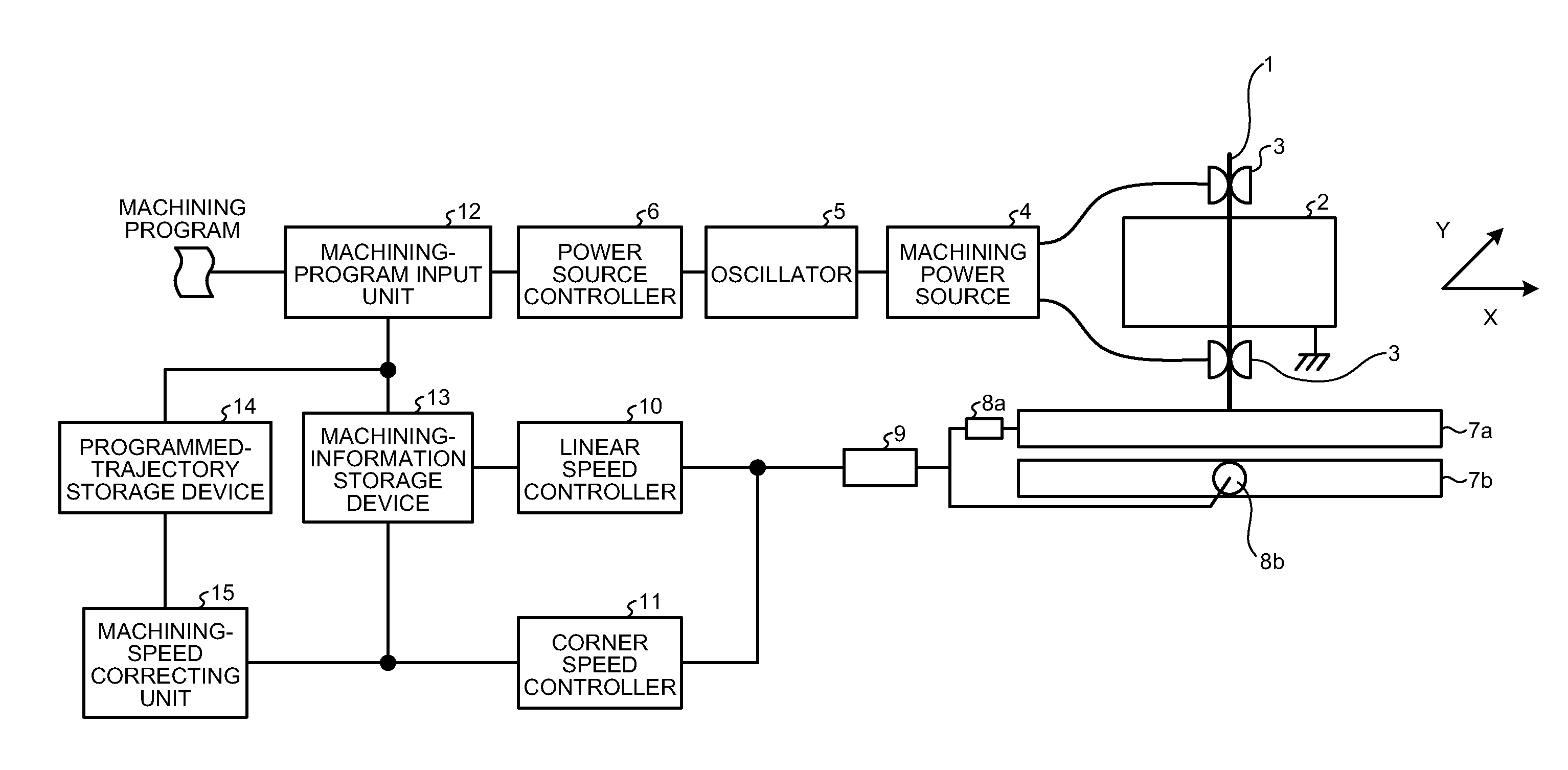
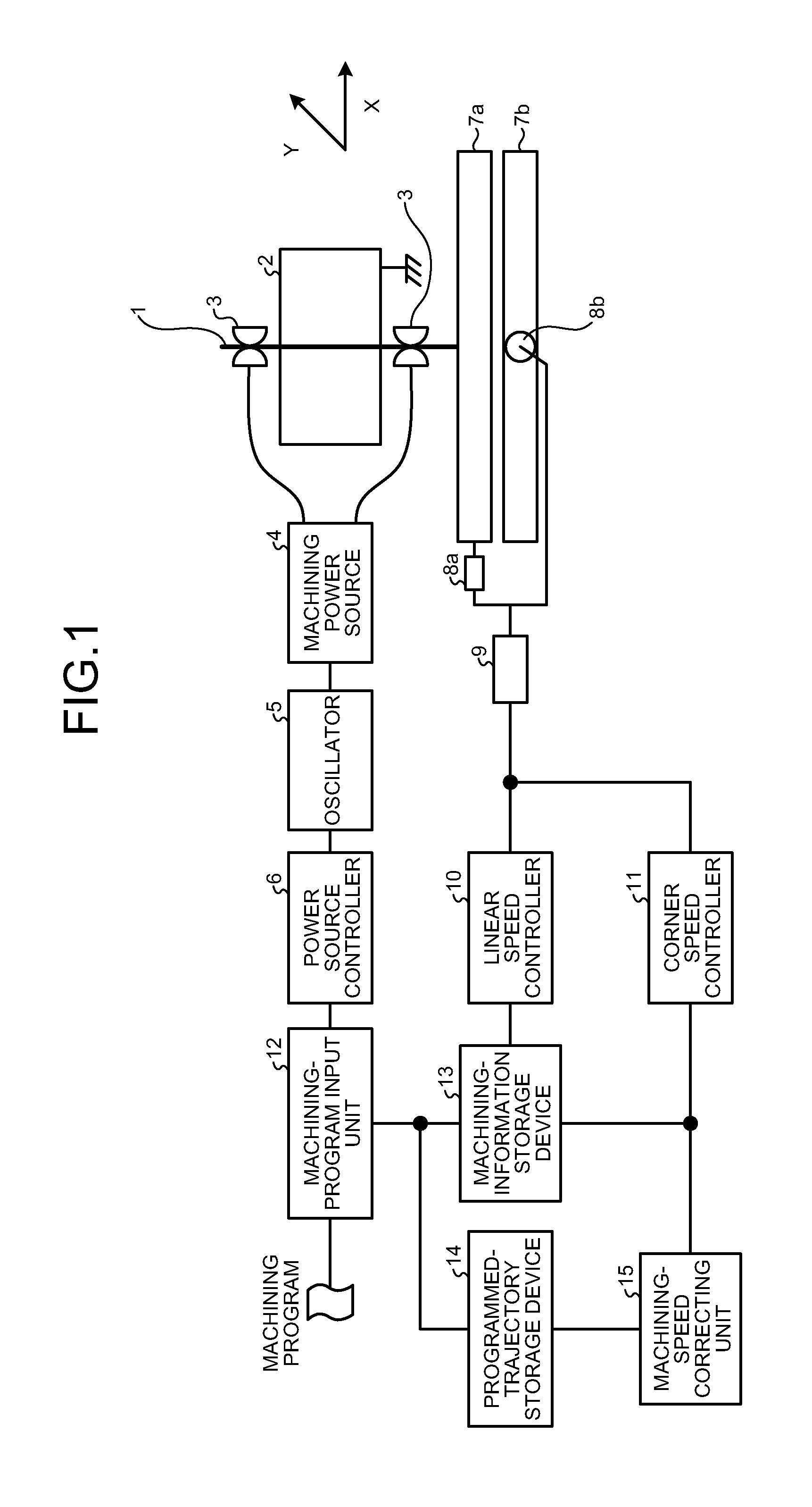
[0032]FIG. 1 is a schematic configuration diagram of a wire electric discharge machining apparatus according to a first embodiment of the present invention. The wire electric discharge machining apparatus according to the present embodiment is a penetration-type wire electric discharge machining apparatus that machines a workpiece 2 into a desired shape by using a wire electrode 1 in a machining tank filled with machining fluid. The wire electric discharge machining apparatus according to the present embodiment can be appropriately changed based on an outline explained below by persons skilled in the art. Therefore, explanations of the present embodiment should be understood widely as contents disclosed relating to the corresponding technical field, and do not limit the present invention.
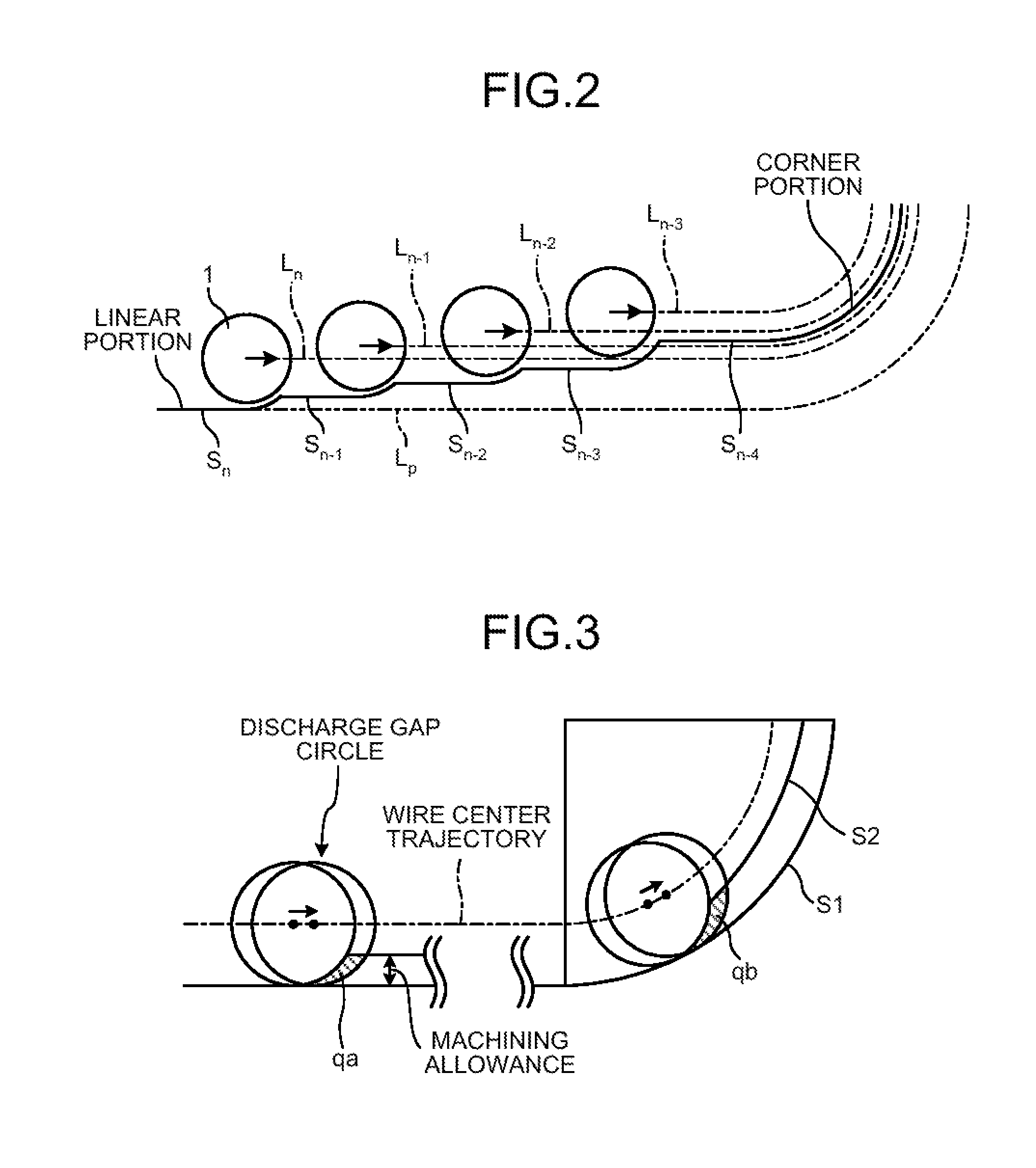
[0033]The wire electrode 1 is guided by wire guides appropriately arranged vertically at an interval, and moves downward, for example. The workpieces 2 having a certain board thickness are arranged ...
second embodiment
[0058]FIG. 10 is a schematic configuration diagram of a wire electric discharge machining apparatus according to a second embodiment of the present invention. The wire electric discharge machining apparatus according to the present embodiment is characterized by including a downtime correcting unit 21 that corrects discharge downtime, during which discharge is suspended. Parts identical to those in the first embodiment described above are denoted by like reference numerals and redundant explanations thereof will be omitted. The downtime correcting unit 21 functions as a machining-condition correcting unit that corrects discharge downtime, which is a machining condition in each machining stage, according to the circular arc radius of a portion corresponding to the corner portion of the programmed trajectory.
[0059]When the machining accuracy cannot be completely improved by the machining speed calculated by the corner speed controller 11, the discharge downtime in the corner portion i...
third embodiment
[0061]FIG. 11 is a schematic configuration diagram of a wire electric discharge machining apparatus according to a third embodiment of the present invention. The wire electric discharge machining apparatus according to the present embodiment is characterized by including an offset correcting unit 31 that corrects an offset amount of the wire center trajectory from the programmed trajectory. Parts identical to those in the first embodiment described above are denoted by like reference numerals and redundant explanations thereof will be omitted. The offset correcting unit 31 functions as a machining-condition correcting unit that corrects the offset amount, which is a machining condition in each machining stage, according to the circular arc radius of a portion corresponding to the corner portion of the programmed trajectory.
[0062]When the machining accuracy cannot be completely improved by the machining speed calculated by the corner speed controller 11, the offset amount in the corn...
PUM
| Property | Measurement | Unit |
|---|---|---|
| Speed | aaaaa | aaaaa |
| Radius | aaaaa | aaaaa |
Abstract
Description
Claims
Application Information
 - R&D
- Intellectual Property
- Life Sciences
- Materials
- Tech Scout
- Unparalleled Data Quality
- Higher Quality Content
- 60% Fewer Hallucinations
Browse by: Latest US Patents, China's latest patents, Technical Efficacy Thesaurus, Application Domain, Technology Topic, Popular Technical Reports.
© 2025 PatSnap. All rights reserved.Legal|Privacy policy|Modern Slavery Act Transparency Statement|Sitemap|About US| Contact US: help@patsnap.com


