
Actuating device with shift carrage lock

a technology of actuating device and shift carrage lock, which is applied in the direction of mechanical control device, manual control with single controlling member, instruments, etc., can solve the problems of increasing the kinetics of the selector lever, increasing the cost of parts, and complicated and sophisticated blocking mechanisms, and achieves simple constructive design.

Inactive Publication Date: 2011-09-22
ZF FRIEDRICHSHAFEN AG
View PDF15 Cites 6 Cited by
  • Summary
  • Abstract
  • Description
  • Claims
  • Application Information

AI Technical Summary

Benefits of technology

[0011]Based on this background, the inventive task is to create an actuating device for an automatic transmission with the blocking mechanism to inhibit the separation between selector lever and transmitting element, while the selector lever is positioned in the sequential shift lane, can be constructively, significantly simplified, whereby, at the same time, actuation under all operating conditions should be safe and smooth. Another task of the invention is to reduce the cost, as compared to the known state of the art, and simplify construction of the actuating devices.

Problems solved by technology

Such kinematic release of the selector lever from the shift carriage, and the simultaneous blocking of the shift carriage, relative to the enclosure of the actuating device, leads to configurations known art with mechanically complicated and sophisticated blocking mechanisms with numerous meshing parts.
Hereby, it is also required, due to potentially larger misapplied forces by the selector lever, that especially the blocking configuration needs to be designed as very robust, causing the use of more expensive parts.
Another problem of the described, known actuating devices is the fact that, because of a robust design and construction of the blocking mechanism, due to potentially larger forces, the selector lever kinetics becomes stiffer and requires more force, therefore, reducing the ease of use.

Method used


Image

  • Actuating device with shift carrage lock
  • Actuating device with shift carrage lock
  • Actuating device with shift carrage lock

Examples


Embodiment Construction

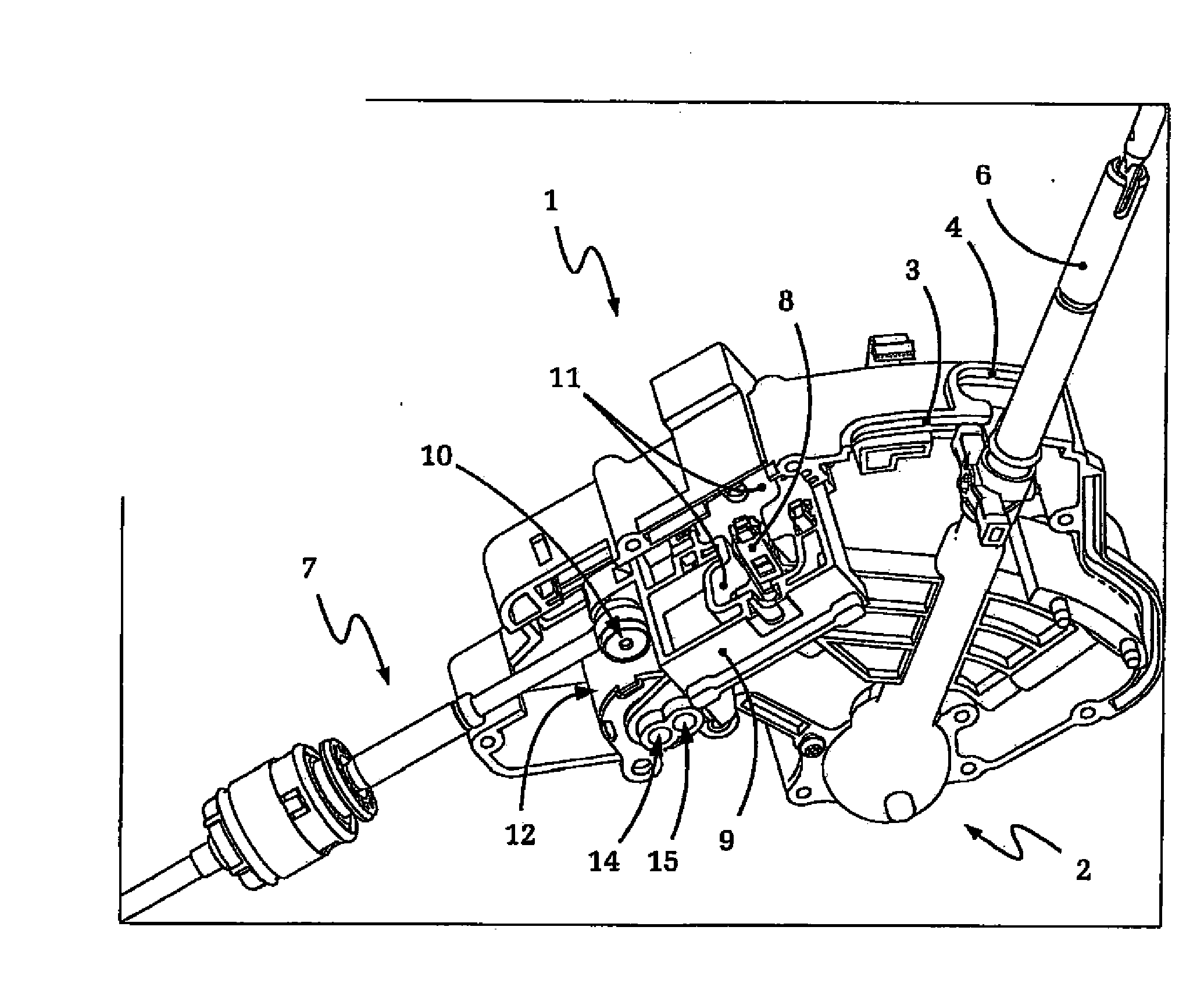
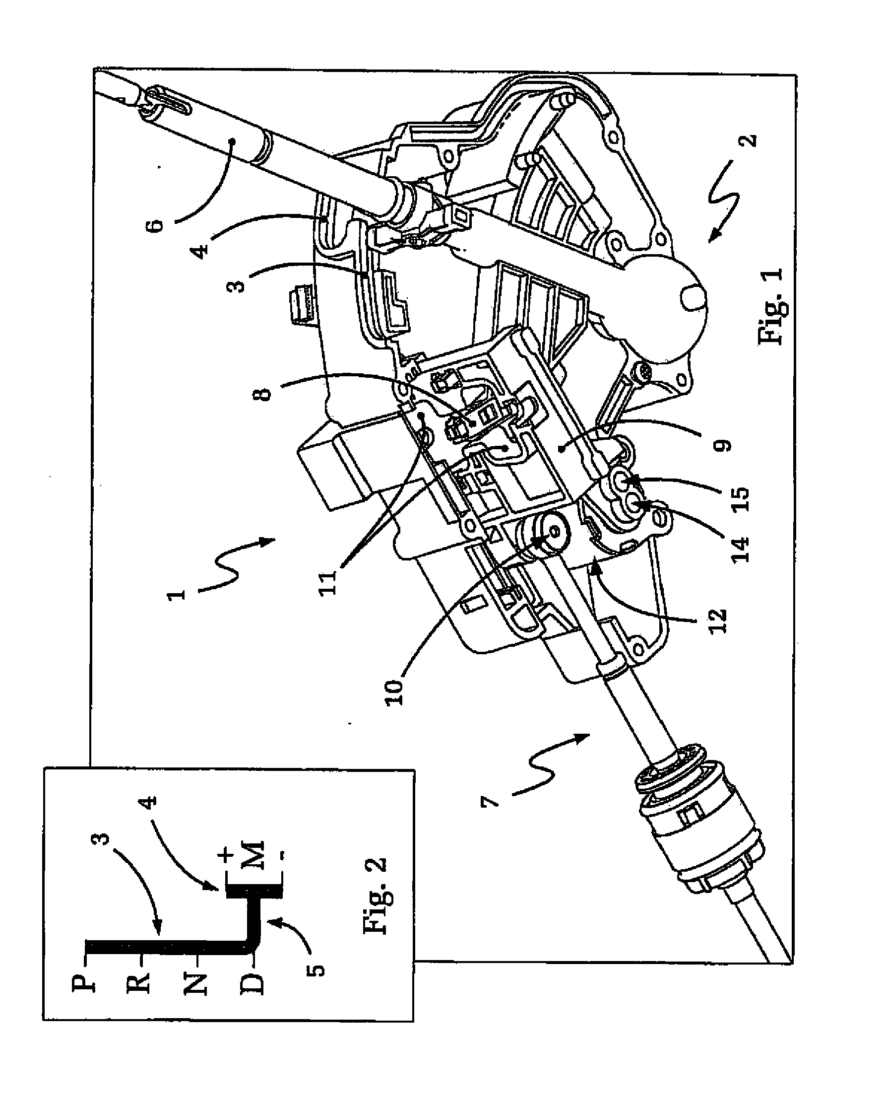
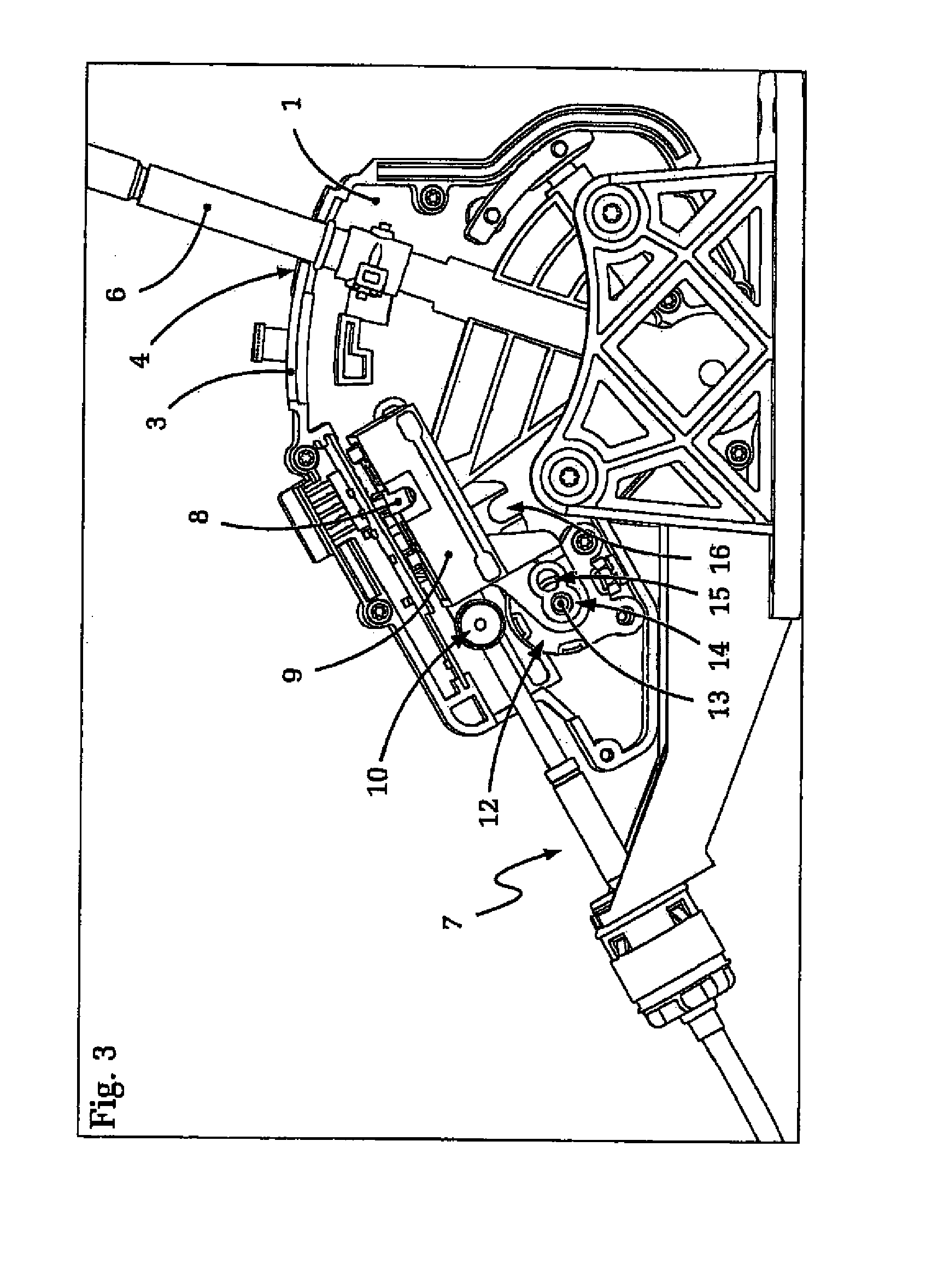
[0035]In FIG. 1, an embodiment of an actuation device for an automatic transmission, in accordance with the present invention, is presented. First shown in the presentation of FIG. 1 is an open lever housing 1 having a lever bearing 2, a sliding lane 3, 4, as well as a lever 6 which accommodates a knob, not shown, of the selector lever of the actuator device.

[0036]FIG. 1 also shows the lever end of the transmitting element, in the form of an embodiment of a pull cable 7, which transfers the shift commands of the actuating device to the transmission of the vehicle. FIG. 2 shows the shift scheme of the actuating device. One can recognize the automatic shift lane 3, the sequential shift lane 4 for manually changing the shift position, as well as the selector lane 5 for the changing, by way of the lateral movement of the selector lever, between the automatic shift lane 3 and the sequential shift lane 4.

[0037]The transmission of the shift commands, in the presented embodiment, occurs—whe...


PUM


Abstract

An actuating device for transmitting shift commands to an automatic gearbox of a motor vehicle. The actuating device comprises a selector lever which is movable in a selector lane between an automatic shift lane and a sequential shift lane, a shift carriage for transmitting the shift commands to a gearbox transmission element, a separating device for separating the force transmission between the selector lever and the shift carriage, and a locking device for blocking the selector lever in at least one selector lever position. The locking device is set up to block the shift carriage. The shift carriage can be blocked not only in the shift-lock positions but also in the position of the shift carriage which corresponds to the selector lane position of the selector lever.

Description

[0001]This application is a National Stage completion of PCT / DE2008 / 050021 filed[0002]Jul. 30, 2008, which claims priority from German patent application serial no. 10 2007 038 495.7 filed Aug. 14, 2007.FIELD OF INVENTION[0003]The invention relates to an actuating device for transmitting shift commands to an automatic transmission of a.BACKGROUND OF INVENTION[0004]A similar type of activating device is known to the applicant, for instance, from patent documentation DE 102 52 009 B4. The known actuator device comprises a selector lever which is movable in a selector lane, between an automatic shift lane and a sequence shift lane. The known actuating device also comprises a kinematic transmitter having a shift carriage for a detachable coupling of the selector lever motion to a transmission-transmitter element, for instance towards a gear shift rod or towards a pull cable link connected with the transmission.[0005]It is required in such conventional generic actuating devices, which ha...

Claims


Application Information

Patent Timeline
Patent Type & Authority Applications(United States)
IPC IPC(8): F16H59/02
CPCF16H59/0204F16H61/22F16H2059/0239Y10T74/20085Y10T74/20104Y10T74/20067Y10T74/20159Y10T74/2014
Inventor WEIFELS, CARSTEN
Owner ZF FRIEDRICHSHAFEN AG
Learn More