INTRACELLULAR pH IMAGING METHOD AND APPARATUS USING FLURESCENCE LIFETIME

a fluorescence lifetime and imaging method technology, applied in the field of living matter ph measurement, can solve the problems of difficult to make highly accurate evaluation and damage to a measurement target, and achieve the effect of not reducing the spot diameter of excitation and measuring fluorescence lifetime in a very small region

Inactive Publication Date: 2011-09-15
FUJIFILM CORP +1
View PDF5 Cites 2 Cited by
  • Summary
  • Abstract
  • Description
  • Claims
  • Application Information

AI Technical Summary

Benefits of technology

[0110]The advantageous effects of the pH measurement apparatuses 1, 4 and 7, as described above, are achievable also by pH measurement apparatuses in other embodiments that will be described later.
[0111]So far, a case of using a confocal microscope method has been described. As described above, in the confocal microscope method, the spot diameter of excitation light illuminating the substance to be measured is reduced (narrowed), and fluorescence lifetime in a very small region is measured. Further, a measurement position is shifted to perform measurement on a measurement target region of the substance to be measured. However, when it is necessary to generate an image of a wide area depending on the substance to be measured, a wide field method may be used. In the wide field method, the spot diameter of the excitation is not reduced, and information about a wide area of xy plane is obtained at once. Further, the entire area of a screen may be imaged by using, as the detection means, a CCD camera or the like without using the scan means. Further, in this case, if the stage 90 (90′) can be scanned in xy direction, an image of a wider area is obtainable by detecting and combining plural xy plane areas.“Second Embodiment of pH Measurement Apparatus (Fiber Probe)”
[0112]Next, a pH measurement apparatus according to another embodiment of the present invention will be described. The pH measurement apparatuses 1, 4 and 7 in the first embodiment are microscopes. However, a pH measurement apparatus 10 in the second embodiment is a fiber probe. In the descriptions of the present embodiment and the drawings, the same signs will be assigned to elements that have substantially the same functions as those of the first embodiment, and explanations will be omitted.
[0113]As illustrated in FIG. 7, the structure of the pH measurement apparatus 10 is similar to the structure of Embodiment 1, except that the objective lens 21 (31) in the first embodiment is replaced by a bundle fiber 21′ (31′) in the second embodiment.
[0114]In the bundle fiber 21′ (31′), an optical fiber 200 for illumination is arranged substantially at the center. The optical fiber 200 for illumination guides the pulsed excitation L1 toward a central part, and illuminates a predetermined position in the substance D to be measured with the excitation light L1. Further, plural optical fibers 300 for receiving light are arranged so as to surround the outer surface of the optical fiber 200 for illumination. The optical fibers 300 for receiving light receive light L3 including fluorescence Lf emitted, by illumination with the excitation light L1, from autofluorescent material P that acts as coenzyme in oxidation / reduction reaction in vivo, and which is contained in the substance D to be measured. Further, the optical fibers 300 for receiving light guide the light L3 to the time-resolving means 40. In FIG. 7, seven optical fibers 300 for receiving light are illustrated. However, it is not necessary that the number of the optical fibers 300 for receiving light is seven. At least one optical fiber for illumination and at least one optical fiber for receiving light should be provided, and the number of fibers and the fiber diameters may be appropriately selected based on receivable fluorescence intensity or the like.
[0115]The bundle fiber 21′ (31′) is produced by fixing the optical fiber 200 for illumination and the optical fiber or fibers 300 for receiving light together by using an adhesive or the like so that they are arranged at predetermined positions. It is desirable to use an additive having a heat resistance temperature appropriate for the excitation L1 used in measurement. When a heat resistance temperature exceeding 300° C. is required, an inorganic heat-resistant additive is used. Further, the fixed bundle fiber may be used as a fiber probe (not illustrated) by providing the bundle fiber in a long and substantially cylindrical sheath to be inserted into body cavity.

Problems solved by technology

However, since fluorescent dyes are harmful to an organism, there is a risk of damaging a target of measurement.
Further, since fluorescence from plural materials and fluorescence from surroundings are reflected in the result of analysis, it is difficult to make highly accurate evaluation.

Method used


Image

  • INTRACELLULAR pH IMAGING METHOD AND APPARATUS USING FLURESCENCE LIFETIME
  • INTRACELLULAR pH IMAGING METHOD AND APPARATUS USING FLURESCENCE LIFETIME
  • INTRACELLULAR pH IMAGING METHOD AND APPARATUS USING FLURESCENCE LIFETIME

Examples


first embodiment

“First Embodiment of pH Measurement Apparatus (Microscope)”

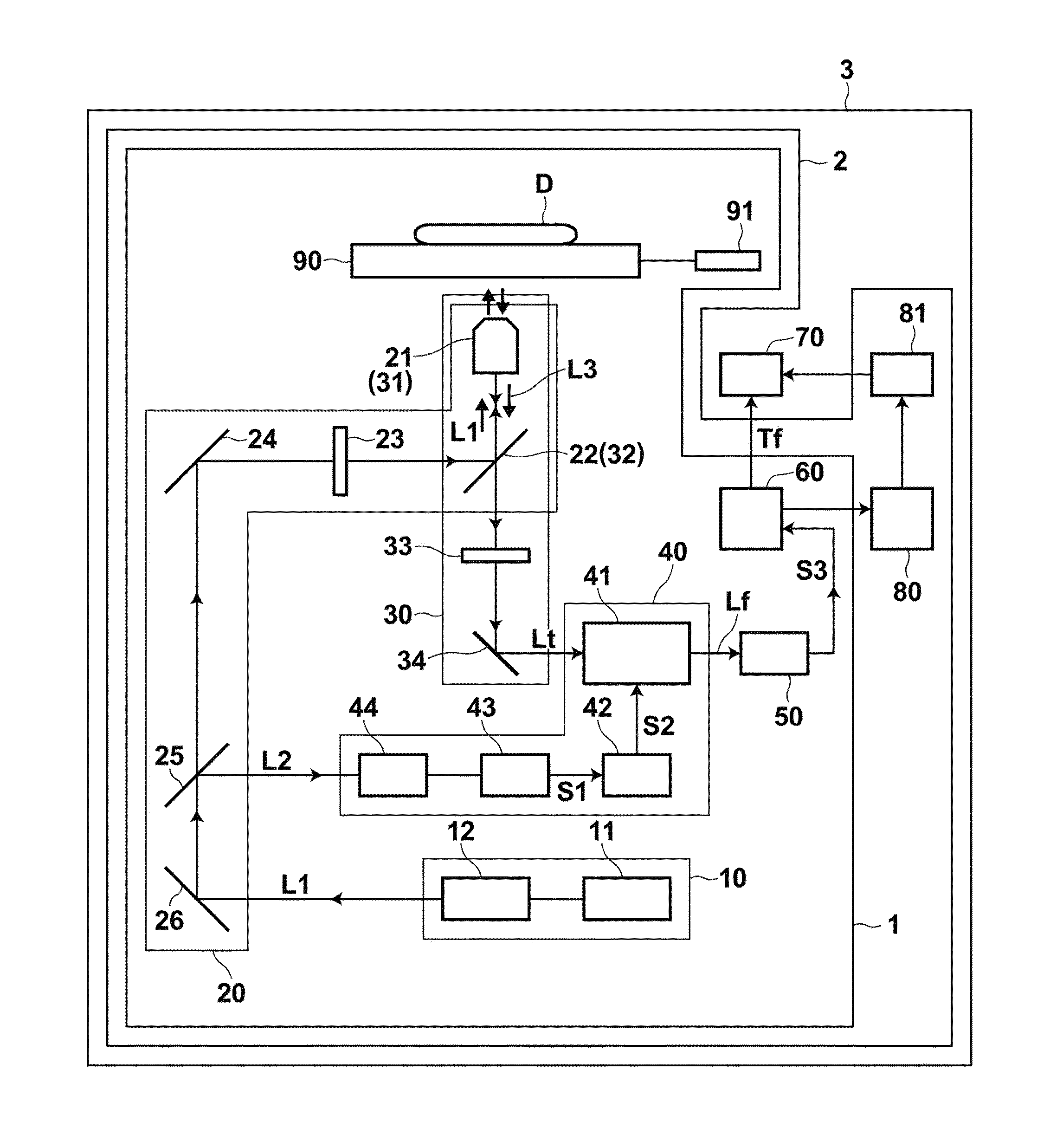
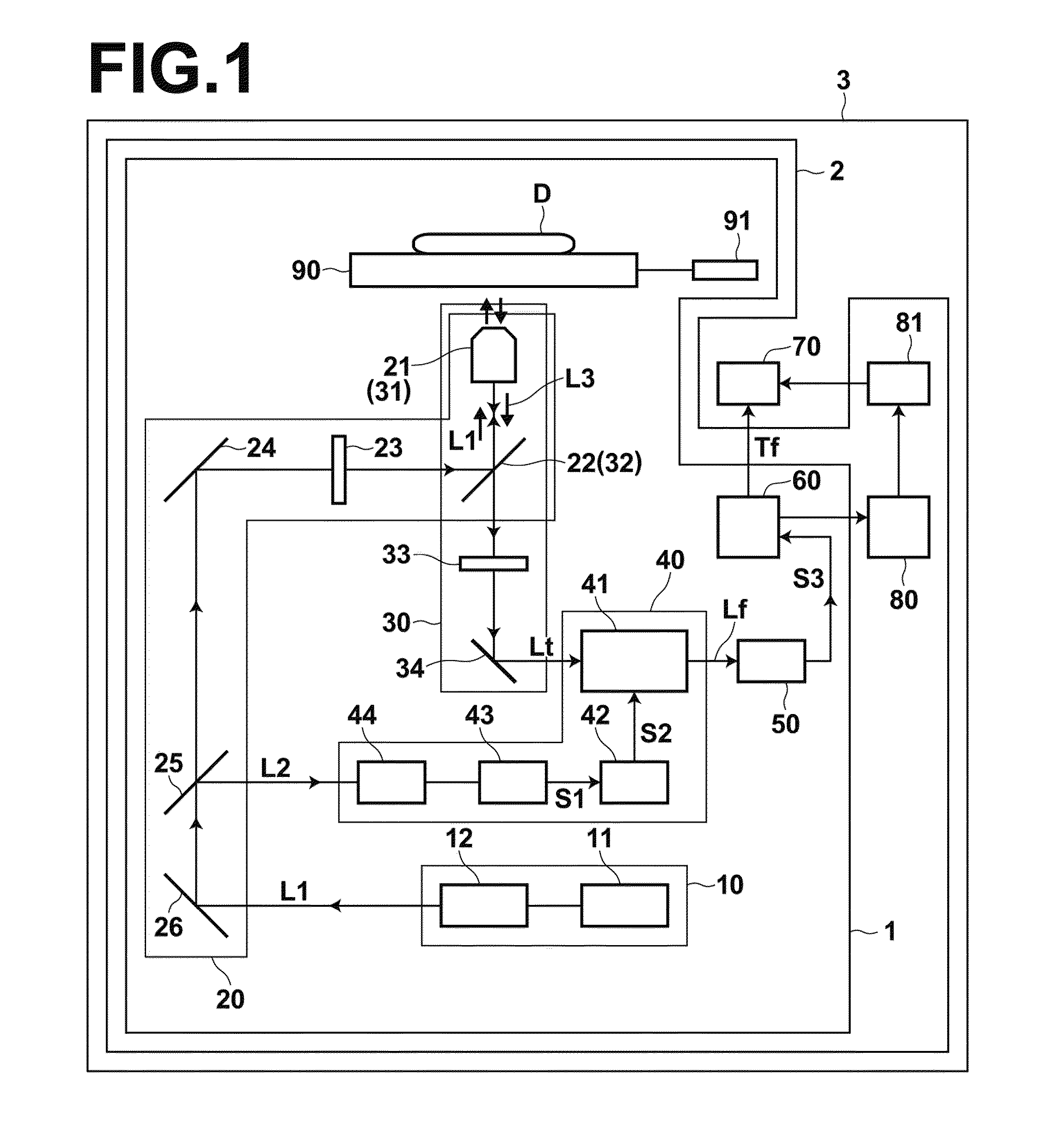
[0068]A pH measurement apparatus and a pH measurement method according to a first embodiment of the present invention will be described with reference to drawings. FIG. 1 is a schematic diagram illustrating the configuration of a pH measurement apparatus 1 according to an embodiment of the present invention. In FIG. 1, each unit is illustrated at an appropriate scale so as to be easily recognized.

[0069]As illustrated in FIG. 1, the pH measurement apparatus 1 outputs pulsed excitation light L1 (hereinafter, referred to as excitation light L1) to substance D to be measured, which is living matter, by an excitation light illumination means 20. Further, the pH measurement apparatus 1 obtains fluorescence by receiving light L3 by a light receiving means 30. The light L3 includes fluorescence Lf emitted, by illumination with the excitation light L1, from fluorescent material P contained in the substance D to be measured. Further, ...

second embodiment

“Second Embodiment of pH Measurement Apparatus (Fiber Probe)”

[0112]Next, a pH measurement apparatus according to another embodiment of the present invention will be described. The pH measurement apparatuses 1, 4 and 7 in the first embodiment are microscopes. However, a pH measurement apparatus 10 in the second embodiment is a fiber probe. In the descriptions of the present embodiment and the drawings, the same signs will be assigned to elements that have substantially the same functions as those of the first embodiment, and explanations will be omitted.

[0113]As illustrated in FIG. 7, the structure of the pH measurement apparatus 10 is similar to the structure of Embodiment 1, except that the objective lens 21 (31) in the first embodiment is replaced by a bundle fiber 21′ (31′) in the second embodiment.

[0114]In the bundle fiber 21′ (31′), an optical fiber 200 for illumination is arranged substantially at the center. The optical fiber 200 for illumination guides the pulsed excitation ...

example 1

[0142]The pH of a HeLa cell that had been cultured, and the pH of which had not been adjusted, was measured by using the microscope-type pH measurement apparatus and the abnormal region detection apparatus, illustrated in FIG. 1. FIG. 9A is a diagram illustrating a fluorescence intensity image of the measured HeLa cell, and FIG. 9B is a diagram illustrating a fluorescence lifetime image of the HeLa cell. Measurement was performed three times on a sample in the same conditions at different measurement regions. The average fluorescence lifetime of three entire images was 2.24 nsec. When pH was calculated based on the obtained fluorescence lifetime by using the equation (1), the pH of the HeLa cell was estimated to be 6.6.


PUM

PropertyMeasurementUnit
pHaaaaaaaaaa
fluorescence lifetime measurementaaaaaaaaaa
fluorescence lifetimeaaaaaaaaaa

Abstract

In a pH measurement method, pulsed excitation light including a wavelength that can excite a predetermined fluorescent material contained in living matter is generated. The fluorescent material acts as coenzyme in oxidation / reduction reaction in vivo. Further, the intensity of the pulsed excitation light does not damage a tissue nor a cell in the living matter, and does not substantially change the pH of the living matter. Further, a predetermined position in the living matter is illuminated with the pulsed excitation light, and light including fluorescence emitted from the fluorescent material excited by illumination with the pulsed excitation light is received. The lifetime of the fluorescence is calculated by time-resolving the intensity of the received fluorescence, and the pH of the living matter is measured based on the lifetime.

Description

BACKGROUND OF THE INVENTION[0001]1. Field of the Invention[0002]The present invention relates to a method for measuring the pH of living matter, a method for detecting an abnormal region based on the pH, a method for analyzing the living matter based on the result of measurement and the result of detection, and apparatuses for carrying out these methods.[0003]2. Description of the Related Art[0004]The values of pH in a cell and a tissue are important factors that regulate functions of an organism (living body), and they are closely related to energy metabolism environment and oxidation / reduction condition in the cell and the tissue. Diseases related to a change in pH in cells and tissues are, for example, cancers, organ hypofunction, and the like.[0005]Cancers and malignant tumors are the leading cause of death in Japan, and most of them are solid cancers, in which cells in organs are cancerized. In treatment of cancers, it is extremely important to detect cancers at early stages an...

Claims


Application Information

Patent Timeline
Patent Type & Authority Applications(United States)
IPC IPC(8): A61B5/1455C12Q1/26C12M1/34
CPCA61B1/043A61B5/0071G01N33/84G01N21/6408A61B5/6852A61B5/0068
Inventor OGIKUBO, SHINYAADACHI, TAKASHIOHTA, NOBUHIRONAKABAYASHI, TAKAKAZU
Owner FUJIFILM CORP
Why Eureka
Try Eureka