Module for on-line vibration detection and adjustment and machining center using the same

Active Publication Date: 2011-09-15
IND TECH RES INST
View PDF10 Cites 43 Cited by
  • Summary
  • Abstract
  • Description
  • Claims
  • Application Information

AI Technical Summary

Benefits of technology

[0006]The present disclosure provides an on-line vibration detection / adjustment module and a tool machining using the same, in which the machining center has a plurality of vibration sensors being arranged at different locations thereon so as to be used for detecting all kinds of machining vibrations during a machining process, and then the detected vibration signals are send to a vibration signal processor for analysis so as to enable a control signal to be issued according to a linear proportion principle and sent to an spindle override interface and a feedrate override interface of the machining center when the result of the detection exceeds a specific threshold, for enabling the spindle speed and the feedrate of the workpiece to be adjusted in an automatic manner with respect to the current working status of the machining center, and thus to prevent any machining vibration effectively from happening during the machining process.
[0007]The present disclosure provides an on-line vibration detection / adjustment module and a tool machining using the same, capable of greatly reducing all kinds of machining vibrations during the performing of a cutting process, by which not only the quality and efficiency of the cutting process can be ensured, but also the lifespan of the cutting tools used in the process can be prolonged, and moreover, they can be adapted for not only the conventional analog servo controller, but also the modern digital servo controller. In addition, since the controlling enabled by the on-line vibration detection / adjustment module of the present disclosure will not have any involvement with the gain of the control circuit embedded in the machining center, but is achieved by the use of control signals issued from the on-line vibration detection / adjustment module that is connected externally to the machining center for enabling the control signals to be fed to the computer numerical control (CNC) unit through the spindle override interface and the feedrate override interface that are originally configured inside the machining center. Thereby, since the control is achieved through an external module without any alteration to any internal structure or system of the machining center, the system stability of the machining center will not be affected.

Problems solved by technology

Most times being unintended and undesirable that can result in imprecise processing and deteriorated surface qualities, machining vibration during the machining of any machining center can be the most troubling problem that the machining center tool industry tries to avoid.
Vibration can result from a number of conditions, acting alone or in combination, such as inproper configuration in cutting parameters, dynamic unbalance in cutting tool assembly, chattering correspond to the relative movement between the workpiece and the cutting tool that can result in waves on the machined surface, thickness variation in workpiece that is to be machined, and resonance, etc.
However, under the performing of a machining process, machining vibrations may occur due to the varying machining conditions or the status variations in the machine parts of the machining center, which can seriously affect the quality of the workpiece to be process as well as the precision of the machining process.
Nevertheless, since the causes of such machining vibrations are hard to predict, it is difficult to control the machining vibrations simply by adjusting the NC code.

Method used


Image

  • Module for on-line vibration detection and adjustment and machining center using the same
  • Module for on-line vibration detection and adjustment and machining center using the same
  • Module for on-line vibration detection and adjustment and machining center using the same

Examples


Embodiment Construction

[0016]For your esteemed members of reviewing committee to further understand and recognize the fulfilled functions and structural characteristics of the disclosure, several exemplary embodiments cooperating with detailed description are presented as the follows.

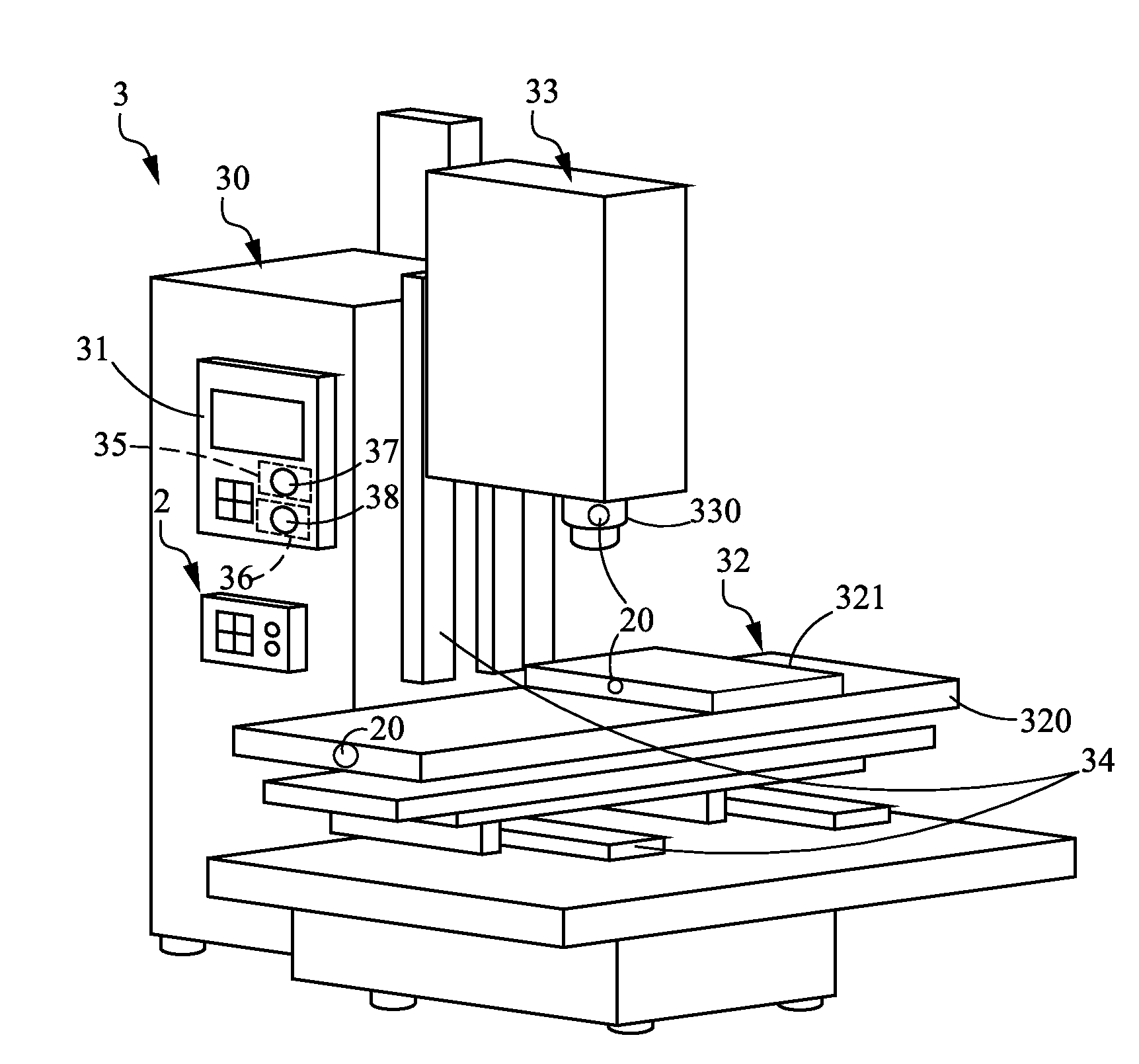
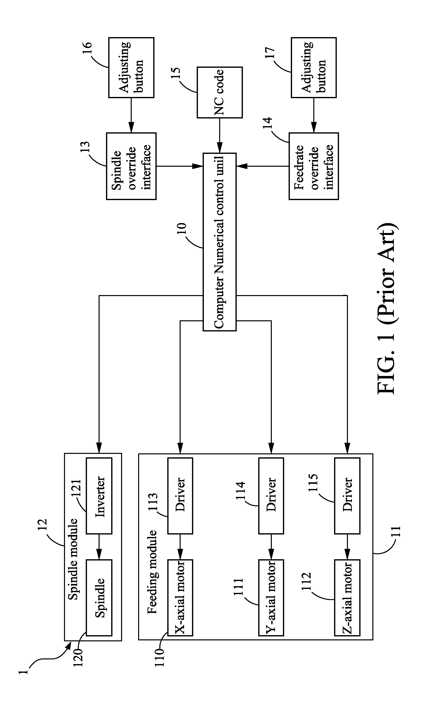
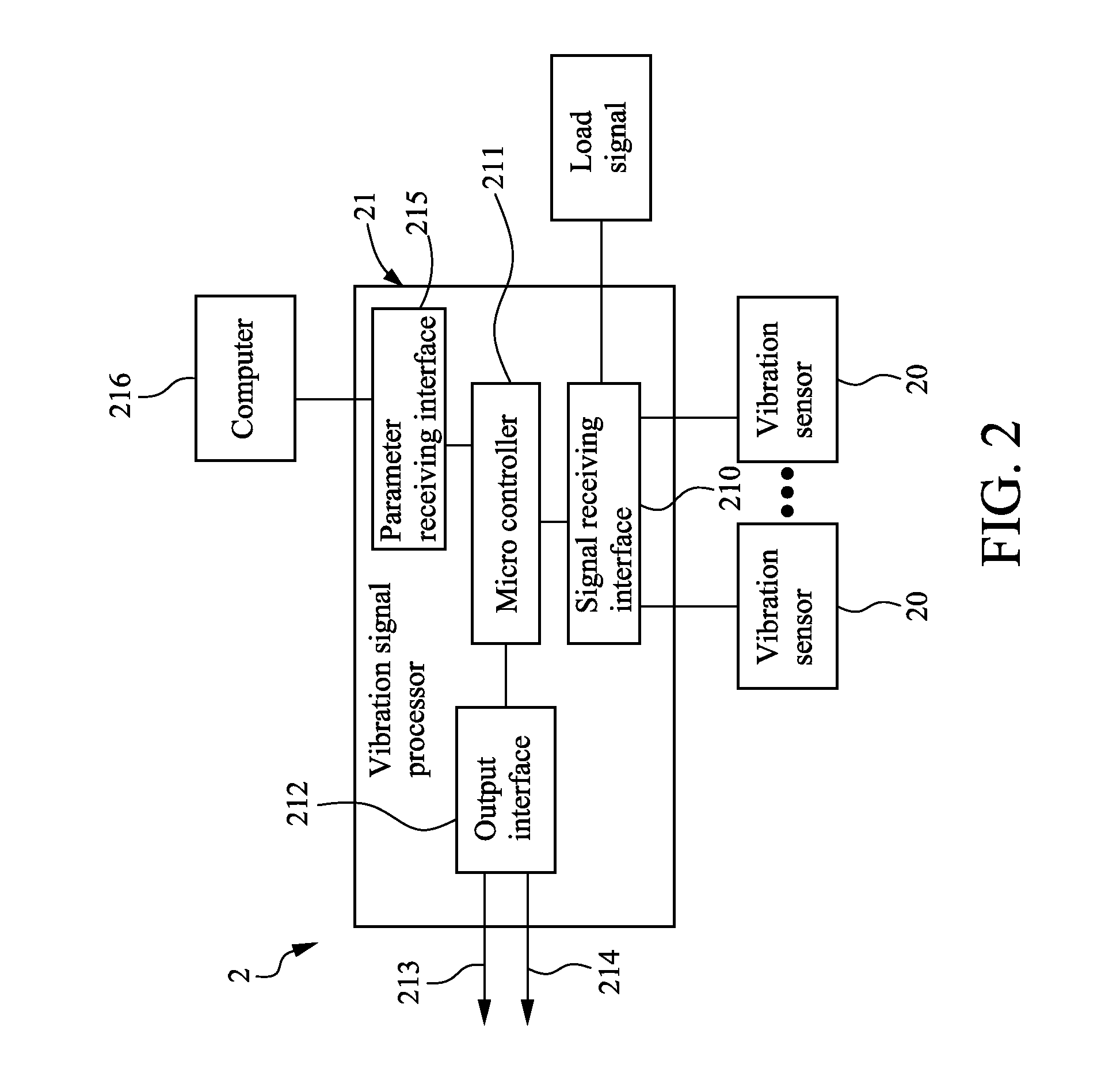
[0017]Please refer to FIG. 2, which is a block diagram illustrating an on-line vibration detection / adjustment module according to an embodiment of the present disclosure. The on-line vibration detection / adjustment module 2 is adapted for a machining center configured with a spindle override interface and a feedrate override interface, whereas the spindle override interface and the feedrate override interface are coupled respectively to two adjusting buttons that are provided for a user to adjust the spindle speed and the feedrate manually in response to the machining status of the machining center in a real-time manner. Generally, by rotating the two adjusting buttons, the CNC codes are changed correspondingly so as to enabli...


PUM

PropertyMeasurementUnit
Speedaaaaaaaaaa

Abstract

A module for on-line vibration detection and adjustment and machining center using the same are provided in the present invention, wherein the module is disposed at the machining center having an interface of feedrate override and an interface of spindle override and the inverter. The module comprises at least one vibration sensor for detecting the vibrating status of the machining center, thereby generating corresponding at least one sensing signal and a processor for processing the at least one sensing signal so as to generate a spindle adjusting signal for the interface of spindle override and the inverter and a feedrate adjusting signal for the interface of the federate override. The computer numerical controller receives the spindle adjusting signal and the feedrate adjusting signal from the interface of the spindle override and federate override respectively and accordingly controls the feedrate and spindle rate of the machining center.

Description

CROSS-REFERENCE TO RELATED APPLICATION[0001]This non-provisional application claims priority under 35 U.S.C. §119(a) on Patent Application No(s). 099107307 filed in Taiwan, R.O.C. on Mar. 12, 2010, the entire contents of which are hereby incorporated by reference.TECHNICAL FIELD[0002]The present disclosure relates to a technique for on-line vibration detection and adjustment, and more particularly, to an on-line vibration detection / adjustment module and a machining center using the same that are capable of controlling the feed rate and the spindle rate of the machining center according to the detection of the on-line vibration detection / adjustment module by the use of a spindle override interface and a feedrate override interface.TECHNICAL BACKGROUND[0003]Most times being unintended and undesirable that can result in imprecise processing and deteriorated surface qualities, machining vibration during the machining of any machining center can be the most troubling problem that the mac...

Claims


Application Information

Patent Timeline
IPC IPC(8): B23Q17/12B23Q5/54B23Q15/007
CPCB23C2250/16Y10T409/300896B23Q17/12G05B19/404G05B2219/37434G05B2219/41117G05B2219/41122G05B2219/41128G05B2219/42077G05B2219/49176G05B19/4065Y10T409/304312Y10T29/49774Y10T408/76B23Q11/0039
Inventor KUO, TZU-HSINHUANG, CHUN-HUNG
Owner IND TECH RES INST
Why Eureka
Try Eureka