
Microwave Antenna Probe Having a Deployable Ground Plane

a microwave antenna and probe technology, applied in the field of microwave ablation surgical system and probe having a deployable ground plane, can solve the problems of probe failure, operative complications, and routine observation of thermal damage to most types of normal cells, and achieve the effect of facilitating the insertion of the needle electrod

Active Publication Date: 2011-09-08
TYCO HEALTHCARE GRP LP
View PDF64 Cites 7 Cited by
  • Summary
  • Abstract
  • Description
  • Claims
  • Application Information

AI Technical Summary

Benefits of technology

[0014]A method of using a surgical ablation system is presented herein, comprising the steps of positioning an ablation probe at an operative site, wherein the ablation probe includes a cannula having therein a deployable ground plane antenna and a distal needle electrode. The ground plane antenna and distal needle electrode are deployed (e.g., extended from the cannula). Electrosurgical energy may be delivered to tissue via the needle electrode to facilitate the insertion of the needle electrode into tiss

Problems solved by technology

However, at slightly elevated temperatures above the approximate range of 43° C. to 45° C., thermal damage to most types of normal cells is routinely observed.
However, such ground planes may have a diameter that is substantially greater than that of the probe shaft, which may preclude the use of laparoscopic treatment, or, require a large puncture to be created in the skin and / or adjacent anatomical structures during such non-invasive procedures.
Additionally, insertion of a needle probe into dense or fibrous tissue may be difficult and place stress on the probe, which may lead to probe failure and operative complications.

Method used


Image

  • Microwave Antenna Probe Having a Deployable Ground Plane
  • Microwave Antenna Probe Having a Deployable Ground Plane
  • Microwave Antenna Probe Having a Deployable Ground Plane

Examples


Embodiment Construction

[0033]Particular embodiments of the present disclosure are described hereinbelow with reference to the accompanying drawings; however, it is to be understood that the disclosed embodiments are merely exemplary of the disclosure, which may be embodied in various forms. Well-known and / or repetitive functions and constructions are not described in detail to avoid obscuring the present disclosure in unnecessary or redundant detail. Therefore, specific structural and functional details disclosed herein are not to be interpreted as limiting, but merely as a basis for the claims and as a representative basis for teaching one skilled in the art to variously employ the present disclosure in virtually any appropriately detailed structure. In addition, as used herein, the term “proximal” shall refer to the end of the instrument that is closer to the user, while the term “distal” shall refer to the end that is farther from the user, as is customary.

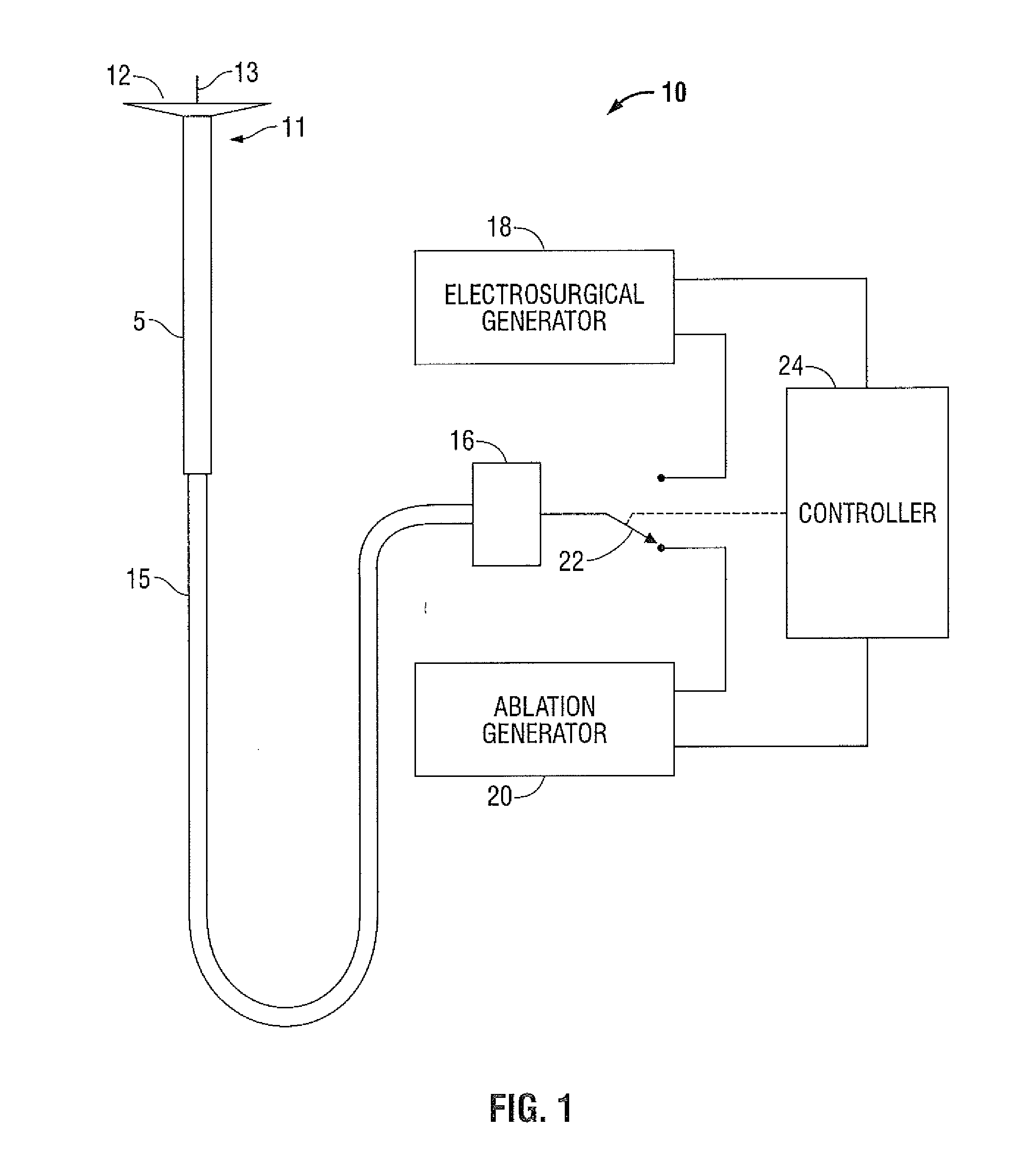
[0034]FIG. 1 shows an embodiment of a microwav...


PUM


Abstract

A surgical ablation system employing an ablation probe having a deployable ground plane is disclosed. The disclosed system includes a source of ablation energy and a source of electrosurgical energy, and a switching assembly configured to select between ablation and electrosurgical modes. The probe includes a cannula having a shaft slidably disposed therein. The shaft includes a deployable ground plane electrode assembly and a needle electrode disposed at distal end of the shaft. As the shaft is extended distally from the cannula, the ground plane electrode unfolds, and the needle electrode is exposed. Electrosurgical energy is applied to tissue via the needle electrode to facilitate the insertion thereof into tissue. Ablation energy is applied to tissue via the needle electrode to achieve the desired surgical outcome. The shaft, ground plane electrode and needle electrode are retracted into the cannula, and withdrawn from the surgical site.

Description

BACKGROUND[0001]1. Technical Field[0002]The present disclosure relates to systems and methods for providing energy to biological tissue and, more particularly, to a microwave ablation surgical system and probe having a deployable ground plane, and methods of use therefor.[0003]2. Background of Related Art[0004]Energy-based tissue treatment is well known in the art. Various types of energy (e.g., electrical, ultrasonic, microwave, cryogenic, thermal, laser, etc.) are applied to tissue to achieve a desired result. Electrosurgery is a technique of using alternating current electrical signals, using a carrier frequency in the approximately 200 kHz-3.3 MHz range, in connection with surgical instruments, to cut or coagulate biologic tissue endogenically. This electrosurgical signal can be a sinusoidal waveform operating in a continuous mode at a 100% duty cycle, or pulse modulated at a duty cycle of less than 100%. Typically, electrosurgical signals are operated at 100% duty cycle for max...

Claims


Application Information

Patent Timeline
IPC IPC(8): A61B18/18A61B18/14
CPCA61B5/0422A61B18/1477A61B18/1815A61B2017/00867C08L2201/12A61B2018/1475A61B2018/162A61B2018/1869A61B2019/306A61B2018/00958A61B2090/036A61B5/287A61B18/16A61B18/18A61B2018/00107A61B2018/00577
Inventor PRAKASH, MANI N.ROSSETTO, FRANCESCABRANNAN, JOSEPH D.
Owner TYCO HEALTHCARE GRP LP
Learn More