
Hybrid Horizontal Axis Energy Apparatus

a technology of horizontal axis and energy apparatus, which is applied in the direction of wind motor with solar radiation, electric generator control, greenhouse gas reduction, etc., can solve the problems of limited electrical energy production, insufficient wind power generation from wind turbines, and high uncertainty of wind power force in direction, magnitude and consistency,

Active Publication Date: 2011-09-08
LEE WILLIAM EDWARD +1
View PDF12 Cites 19 Cited by
  • Summary
  • Abstract
  • Description
  • Claims
  • Application Information

AI Technical Summary

Benefits of technology

[0009]The hybrid horizontal axis energy apparatus disclosed herein addresses the above stated needs for harnessing multiple sources of energy, for example, wind energy, solar energy, etc., for generating electrical energy, while being interconnected to additional apparatuses to produce additional electrical energy. This is achieved by providing solar devices that rotate to increase the efficiency and the electrical energy output during operation of the hybrid horizontal axis energy apparatus. Moreover, the hybrid horizontal axis energy apparatus disclosed herein has two or more rotor assemblies interconnected via drive mechanisms. Furthermore, the hybrid horizontal axis energy apparatus disclosed herein prevents build up of light attenuating particles, for example, dust, on the solar devices provided in the hybrid horizontal axis energy apparatus to increase their efficiency.
[0013]In an embodiment, the central rotatable element that houses the solar devices is disposed on opposing sides of the rotor assembly for increasing exposure of the solar devices to sunlight. In another embodiment, the solar devices are configured as plates spaced apart at predetermined distances on opposing sides of the rotor assembly for increasing exposure of the solar devices to sunlight. The solar devices, in this embodiment, are rigidly connected to and disposed on an extended stationary axle of the frame. In this embodiment, the motor is centrally located within a space defined by each central rotatable element on opposing sides of the rotor assembly.
[0015]The solar devices are rigidly attached to the curved section of the central rotatable element of the rotor assembly, for example, by adhesion, clamping, threading, or by a support fixture that holds the solar devices onto the central rotatable element. In an embodiment, the solar devices are of a spherical shape to receive solar energy from multiple sunlight directions. The solar devices are exposed to sunlight and convert solar energy of sunlight into electrical energy. In an embodiment, the hybrid horizontal axis energy apparatus disclosed herein further comprises a weatherproof seal that encapsulates the solar devices on the central rotatable element of the rotor assembly for protecting the solar devices from water and weather conditions.
[0017]The electrical generator is connected proximal to the rotor assembly and in engageable communication with the rotor assembly via the drive mechanism. The drive mechanism rigidly attached to the rotor assembly is, for example, a gear ring or a friction wheel, and a drive mechanism rigidly attached to the electrical generator is a corresponding gear ring or a roller wheel respectively. When the rotor assembly rotates, the drive mechanism rigidly attached to the rotor assembly engageably communicates with the drive mechanism rigidly attached to the electrical generator to rotate the electrical generator. The electrical generator converts mechanical energy produced by the rotation of the rotor assembly to electrical energy. The hybrid horizontal axis energy apparatus thereby produces energy. Furthermore, the rotation of the rotor assembly prevents build up of light attenuating particles for example, dust, on the solar devices rigidly attached to the central rotatable element of the rotor assembly, thereby increasing efficiency of the solar devices.
[0018]The body of the motor and the solar devices are rigidly attached to the central rotatable element. Hence, the rotation of the motor tends to rotate the solar devices while rotating the rotor assembly. This rotation of the solar devices while converting solar energy into electrical energy provides an extended life span or better mean time before failure (MTBF) of the solar devices, since the solar devices operate at a lower temperature, thereby offering better electrical energy output. The solar devices are cooled down by ambient air impinging on the solar devices during the rotation of the solar devices. Hence, the life of the solar devices and the efficiency of the solar devices are enhanced over a longer period of time, and the replacement frequency of the solar devices with new solar devices is decreased.

Problems solved by technology

The force of wind is highly unpredictable in terms of direction, magnitude, and consistency.
Consequently, the force of wind may be inadequate to generate sufficient electrical energy from the wind turbine and meet the requirements of a user.
This singular usage of the wind turbine leads to a limited production of electrical energy, which is again insufficient to meet the requirements of the user.
Furthermore, solar devices provided in wind turbines for generating electrical energy from solar energy, are often exposed to dust and other light attenuating particles, which reduce their efficiency.
This leads to a decrease in efficiency of conversion of solar energy into electrical energy by the solar devices.

Method used


Image

  • Hybrid Horizontal Axis Energy Apparatus
  • Hybrid Horizontal Axis Energy Apparatus
  • Hybrid Horizontal Axis Energy Apparatus

Examples


Embodiment Construction

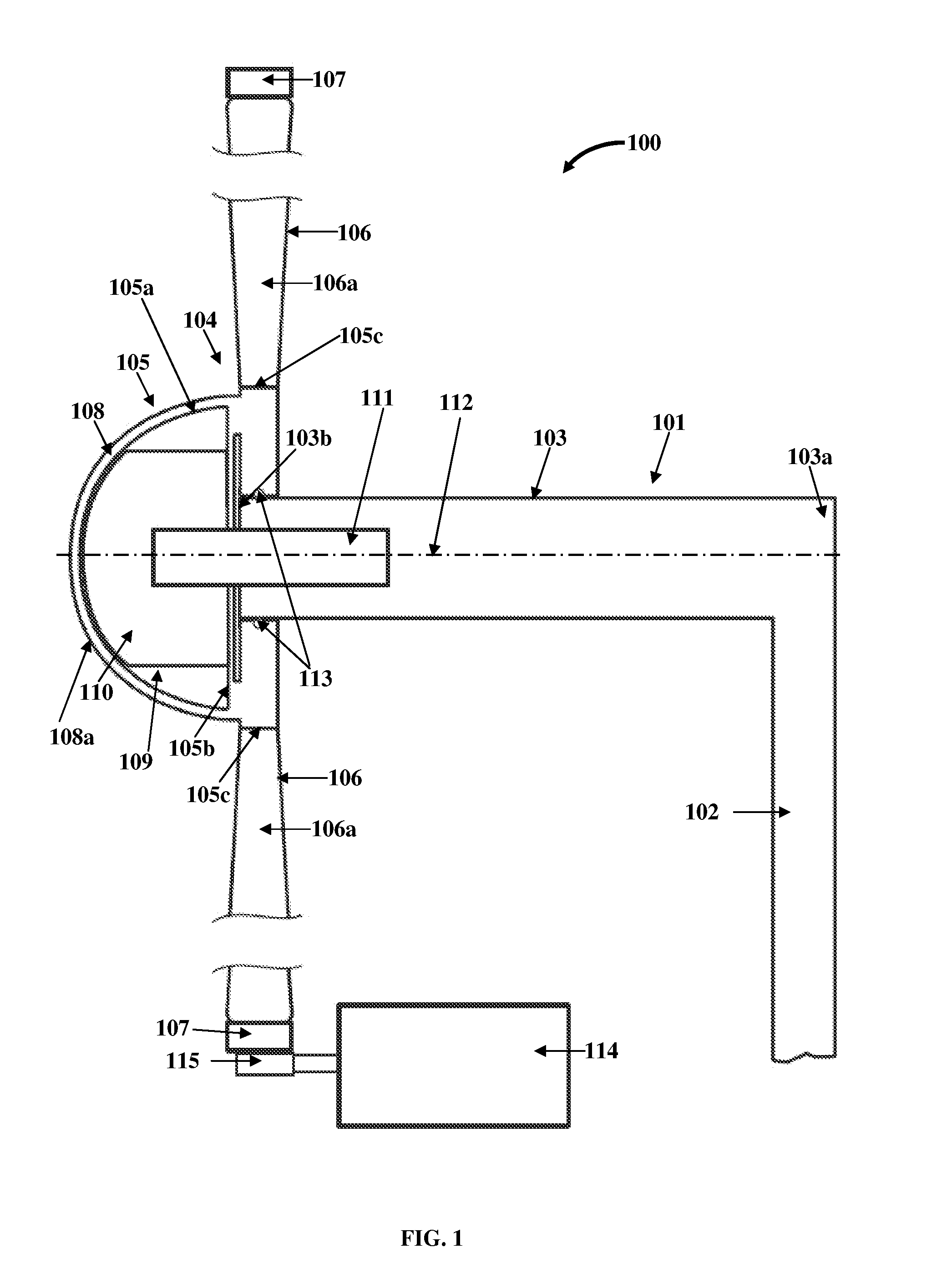
[0042]FIG. 1 exemplarily illustrates a side sectional view of a hybrid horizontal axis energy apparatus 100. The hybrid horizontal axis energy apparatus 100 disclosed herein comprises a frame 101, a rotor assembly 104, a drive mechanism 107, one or more solar devices 108, a motor 109, and an electrical generator 114. The frame 101 is configured to receive the rotor assembly 104. In an embodiment as exemplarily illustrated in FIG. 1, the frame 101 comprises a vertical tower 102 and a stationary axle 103. The stationary axle 103, having a first end 103a and a second end 103b, is perpendicularly connected to the vertical tower 102. The first end 103a of the stationary axle 103 is rigidly connected to the vertical tower 102.

[0043]The rotor assembly 104 of the hybrid horizontal axis energy apparatus 100 is rotatably connected to the frame 101 and rotates in response to a force of wind and the power generated by the solar devices 108. The rotor assembly 104 is rotatably connected to the s...


PUM


Abstract

A hybrid horizontal axis energy apparatus comprising a frame and a rotor assembly rotatably connected to the frame is provided. A drive mechanism is rigidly attached on the rotor assembly and is in engageable communication with an adjacent drive mechanism of an adjacent rotor assembly for rotating the adjacent rotor assembly. One or more solar devices, rigidly attached to the rotor assembly, produce electrical energy. A motor is electrically connected to the solar devices and rotates the rotor assembly about a horizontal axis of the frame on receiving the electrical energy produced by the solar devices. An electrical generator, in engageable communication with the rotor assembly via the drive mechanism, converts mechanical energy produced by the rotation of the rotor assembly to electrical energy. The rotation of the rotor assembly removes light attenuating particles from the solar devices housed on the rotor assembly, thereby increasing efficiency of the solar devices.

Description

CROSS REFERENCE TO RELATED APPLICATIONS[0001]This application claims the benefit of provisional patent application No. 61 / 311,384 titled “Hybrid Horizontal Axis Energy Apparatus”, filed on Mar. 8, 2010 in the United States Patent and Trademark Office.[0002]The specification of the above referenced application is incorporated herein by reference in its entirety.BACKGROUND[0003]A conventional horizontal axis wind turbine harnesses the energy of wind and converts the energy to a form of mechanical energy. The mechanical energy may further be converted to electrical energy based on the application for which the wind turbine is used. The force of wind is highly unpredictable in terms of direction, magnitude, and consistency. Consequently, the force of wind may be inadequate to generate sufficient electrical energy from the wind turbine and meet the requirements of a user. Hence, there is a need for generating electrical energy from more than one source of energy to meet the requirements ...

Claims


Application Information

Patent Timeline
IPC IPC(8): F03D9/00
CPCF03D9/00Y02E10/725F03D1/02F03D9/007F03D9/11F03D9/25F03D13/20F03D15/10F03D17/00F03D80/70F03D80/82H02S10/12Y02E10/50Y02E10/72Y02E10/728Y02E70/30
Inventor LEE, WILLIAM EDWARDPIENKOWSKI, ROBERT F.
Owner LEE WILLIAM EDWARD
Learn More