
Network device with uninterruptible power supply function

a network device and function technology, applied in the field of network devices, can solve problems such as data damage, fttb architecture is not user-friendly to the user terminal b, and network resources are not normally provided

Inactive Publication Date: 2011-09-01
CONNECTION TECH SYST
View PDF6 Cites 7 Cited by
  • Summary
  • Abstract
  • Description
  • Claims
  • Application Information

AI Technical Summary

Problems solved by technology

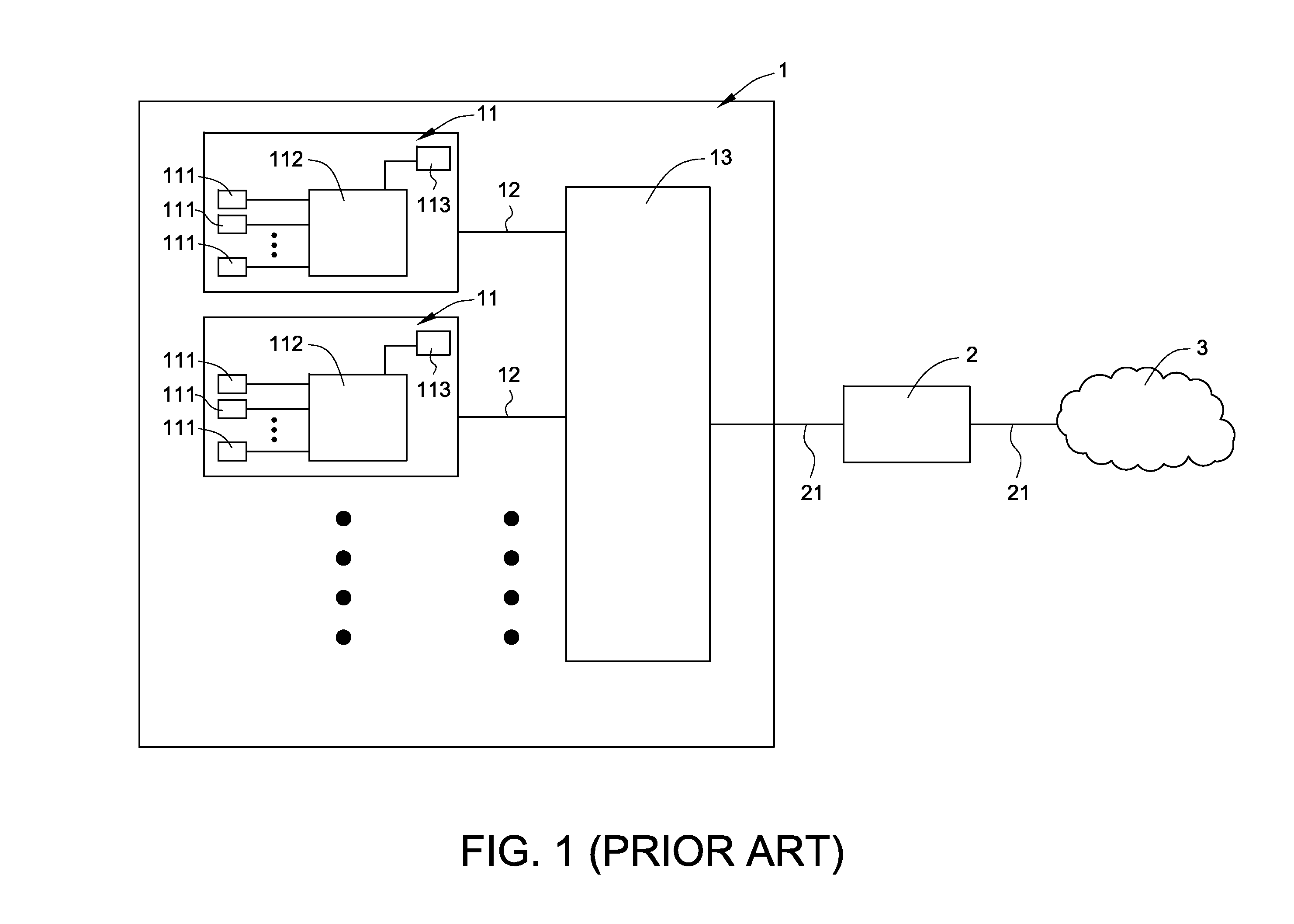
Since the network device 112 of each user terminal 11 is powered by the power source 113 that is provided by a power company, if the electricity provided by the power source 113 is subject to a sudden variation or interruption, the networking resource fails to be normally provided and a data damage problem is possibly incurred.
In other words, the FTTB architecture is not user-friendly to the user terminal 11.
Since the electricity of the uninterruptible power supply is mainly provided to an external load rather than the network adapting module, if the network adapting module is powered off, the communication with the network is interrupted.
Although the network equipment can provide stable power to the smart user terminals to prevent the sudden power failure from interrupting the networking tasks, there are still some drawbacks.
For example, when one of the smart user terminals intends to perform networking communication with other user terminals through the individual network device, if the electricity to the individual network device is interrupted, the individual network device fails to successfully perform networking communication.
In addition, Taiwanese Utility Patent No. 523217 disclosed an uninterruptible power supply apparatus with a communication function.
In addition to the uninterruptible power supply function, this uninterruptible power supply apparatus also has a communication operating function of processing audio, faxing and data signals.
Since the uninterruptible power supply apparatus with a communication function is a electronic communication system and the network terminal is connected by using a RJ45 connector as network connecting port, the communication function of this uninterruptible power supply apparatus fails to be applied to a new generation optical communication system (e.g. an optical fiber network).
From the above discussions, some drawbacks are encountered from the conventional uninterruptible power supply system with the network device and need to be obviated.

Method used


Image

  • Network device with uninterruptible power supply function
  • Network device with uninterruptible power supply function
  • Network device with uninterruptible power supply function

Examples


Embodiment Construction

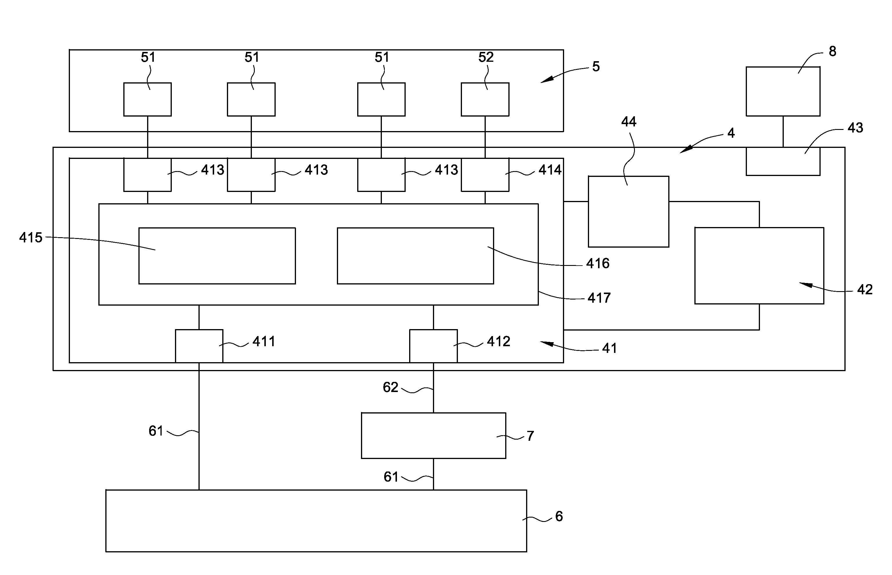
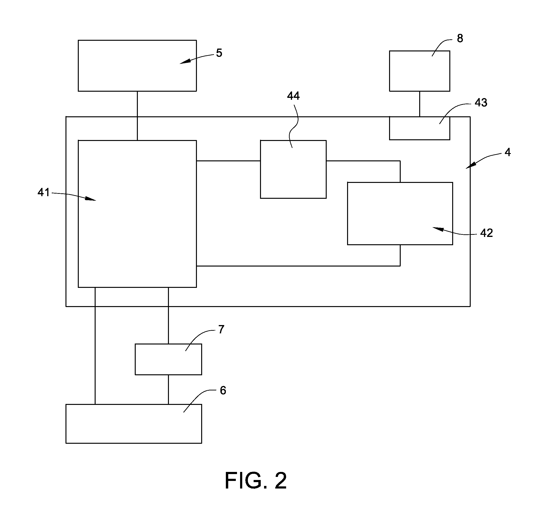
[0026]FIG. 2 is a schematic functional block diagram illustrating a network device according to an embodiment of the present invention. The network device 4 is disposed in a use space (e.g. home or office) of a user terminal. A first end of the network device 4 is in communication with an electronic device 5 at the user terminal. A second end of the network device 4 is in communication with the network equipment of an optical line termination 6 or a network switch 7. The network switch 7 is installed within a community building by the optical line termination 6 (i.e. a network communication service provider). The data packets could be transmitted from the electronic device 5 at the user terminal to the network equipment of the optical line termination 6. Alternatively, the data packets could be transmitted from the network equipment of the optical line termination 6 to the electronic device 5 at the user terminal.

[0027]The network device 4 comprises a network physical transmission u...


PUM


Abstract

A network device with an uninterruptible power supply function is provided. The network device includes a network physical transmission unit, a power connecting part and a backup power supply module. The network physical transmission unit is operated at a user terminal according to a fiber to the home (FTTH) technology or a fiber to the building (FTTB) technology. The power connecting part is in communication with an external power source for receiving electricity from the external power source to operate the network device. If the electricity transmitted from the external power source to the network device is interrupted, the backup power supply provides backup electricity to the network device to maintain normal operation of the network device.

Description

FIELD OF THE INVENTION[0001]The present invention relates to a network device, and more particularly to a network device with an uninterruptible power supply function.BACKGROUND OF THE INVENTION[0002]With increasing development of information industries and rapid growth of high-tech industries, network communication technologies become prevailing. The network communication technologies may facilitate people to communicate with each other more efficiently and free people from the limitation of space and time. By the technology and environment of network communication, multimedia information (e.g. texts, sound, pictures and images) could be transmitted in an interactive manner. Recently, the optical communication system gradually replaces the electronic communication system in order to increase the communicating speed and quality of Internet. Optical fiber is the most common data transmitting medium of the optical communication system because it advantageous for low loss, high bandwid...

Claims


Application Information

Patent Timeline
Patent Type & Authority Applications(United States)
IPC IPC(8): H04J14/00H04B10/00
CPCH02J9/06
Inventor CHEN, YU-HSINYANG, WEI-PING
Owner CONNECTION TECH SYST
Learn More