
Method and system for estimating position with bias compensation

a position estimation and bias compensation technology, applied in the field of method and system for estimating position with bias compensation, can solve the problems of glonass location-determining receivers susceptible to position errors, neither the error-reduction filter approach, nor the raim technique fully address

Active Publication Date: 2011-09-01
DEERE & CO
View PDF11 Cites 29 Cited by
  • Summary
  • Abstract
  • Description
  • Claims
  • Application Information

AI Technical Summary

Benefits of technology

[0006]In accordance with one embodiment, the method and system comprises a primary phase measurement device for measuring a first carrier phase of a first carrier signal (e.g., GPS L1 signal or “L1”) and a second carrier phase of a second carrier signal (e.g., GPS L2 signal or “L2”) received by the location-determining receiver. The first carrier signal (e.g., L1) is transmitted at substantially the same frequency from two or more primary satellites. The second carrier signal (e.g., L2) is transmitted at substantially the same frequency from two or more primary satellites. A secondary phase measurement device measures the third carrier phase of a third carrier signal (e.g., GLONASS G1(K) signal or “G1(K)”) and the fourth carrier phase of fourth carrier signal (e.g., GLONASS G2(K) signal or “G2(K)”). The third carrier signal (e.g., G1(K)) is received at different frequencies from two or more secondary satellites. The fourth carrier signal (e.g., G2(K)) is received at different frequencies from two or more secondary satellites that result in an inter-channel bias between carrier signals from different ones of the secondary satellites observable at the location-determining receiver. A real time kinematic engine estimates a first integer ambiguity set associated with the measured first carrier phase, and a second integer ambiguity set associated with the measured second carrier phase. The real time kinematic engine estimates a third ambiguity set (e.g., third integer ambiguity set) associated with the measured third carrier phase and a fourth ambiguity set (e.g., fourth integer ambiguity set) associated with the measured fourth carrier phase. A compensator is capable of compensating for the inter-channel bias in at least one of the third ambiguity set and the fourth ambiguity set by modeling a predictive filter (e.g., Kalman filter) in accordance with the following inputs or states of the filter: motion data (e.g., position data, velocity data and acceleration data) of the object; troposphere data (e.g., residual troposphere data); ionosphere data; a single difference reference ambiguity set associated with third carrier signals received at the location-determining receiver and a reference station from different secondary satellites (e.g., GLONASS Reference Satellite G1(K) Single Difference Ambiguity or GLN Reference Sat. G1 SD Ambiguity), and a single difference reference ambiguity set associated with fourth carrier signals received at the location-determining receiver and a reference station from different secondary satellites (e.g., GLONASS Reference Satellite G2(K) Single Difference Ambiguity or GLN Reference Sat. G2 SD Ambiguity). An estimator is capable of determining a position of the object based on the measured first carrier phase, the measured second carrier phase, the estimated first integer ambiguity set, the estimated second integer ambiguity set, and at least one of the measured third carrier phase and the measured fourth carrier phase, and at least one of the compensated third ambiguity set (e.g., compensated third integer ambiguity set) and the compensated fourth ambiguity set (e.g., compensated fourth integer ambiguity set).

Problems solved by technology

Because the GLONASS satellites transmit on different frequencies, which may lead to differences in propagation through the ionosphere or troposphere or other errors, the GLONASS location-determining receiver is susceptible to position error from inter-channel bias associated with the different transmission frequencies of satellites.
Neither the error-reduction filter approach, nor the RAIM technique fully addresses the aforementioned problem of imprecise pseudo-range and carrier phase measurements, where the location-determining receiver receives (e.g., transiently) one or more satellite signals of low signal strength or poor signal quality.

Method used


Image

  • Method and system for estimating position with bias compensation
  • Method and system for estimating position with bias compensation
  • Method and system for estimating position with bias compensation

Examples


Embodiment Construction

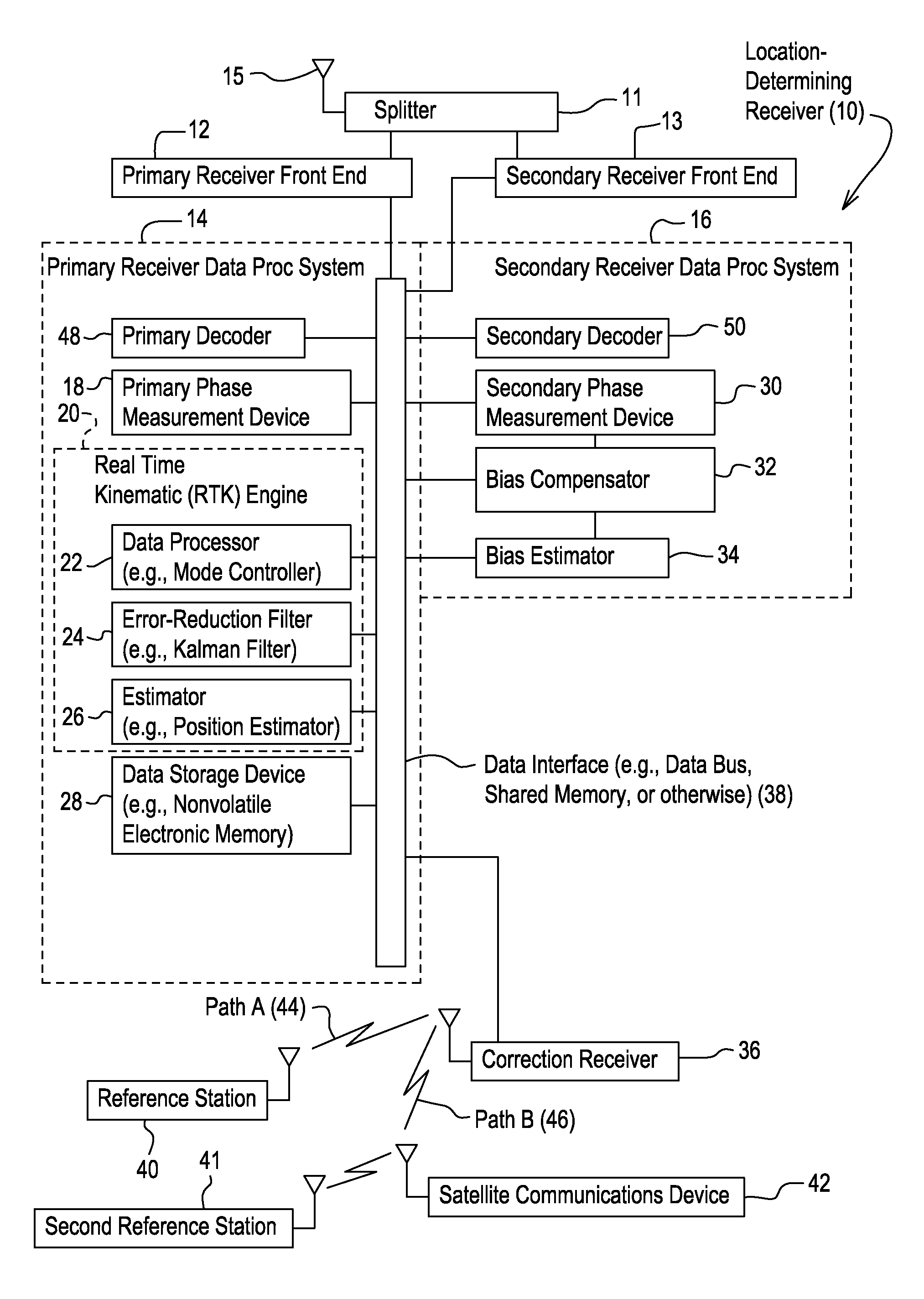
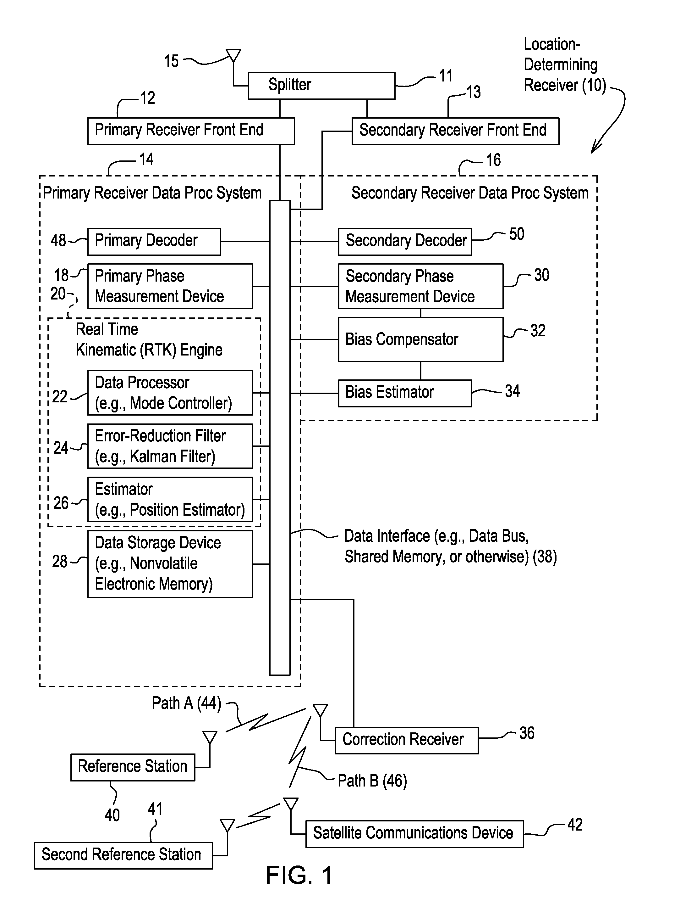
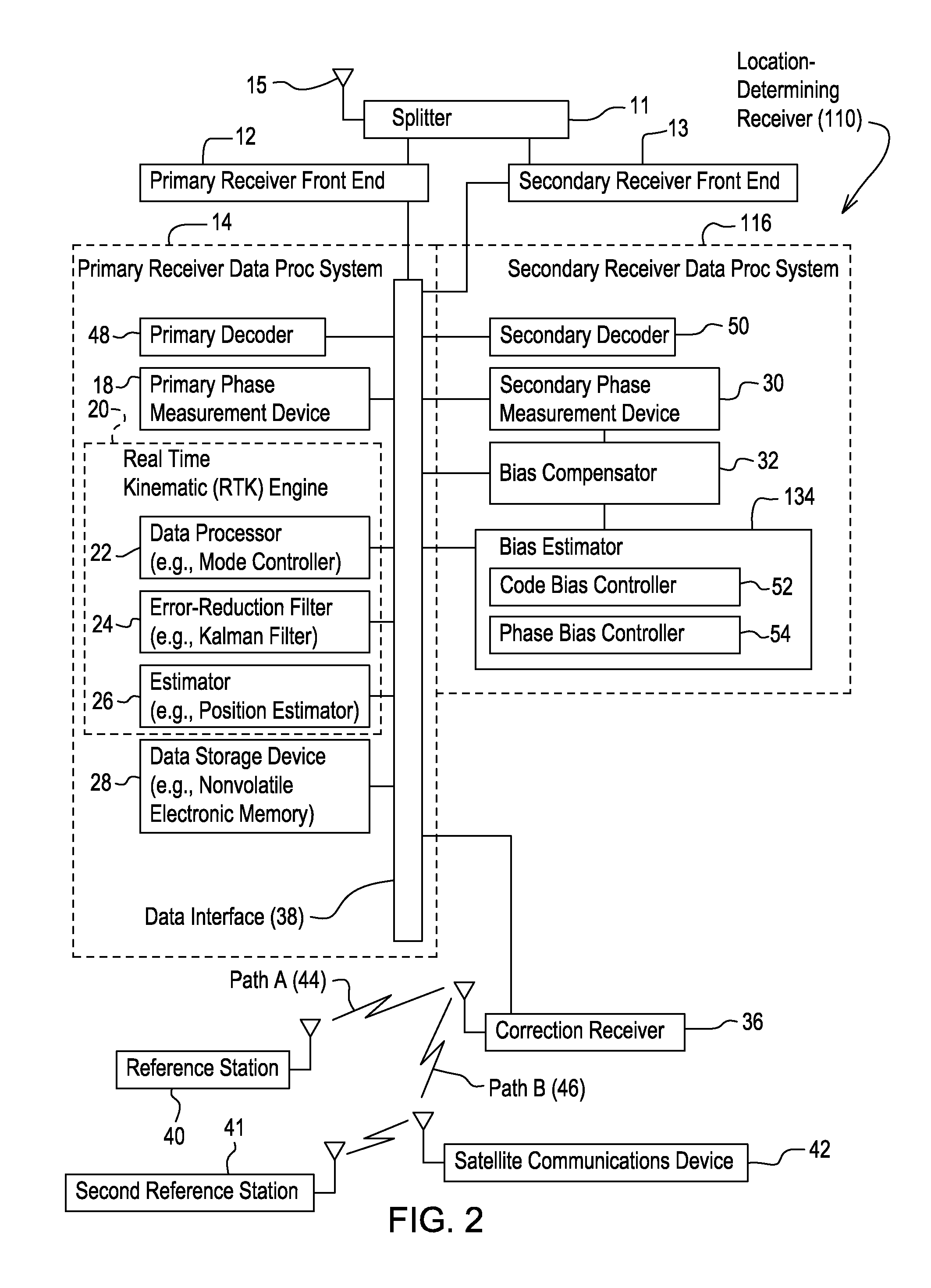
[0023]FIG. 1 illustrates a location-determining receiver 10 that comprises a primary receiver front end 12 coupled to a primary receiver data processing system 14 and a secondary receiver front end 13 associated with a secondary receiver data processing system 16. In one embodiment, the primary receiver front end 12 and the secondary receiver front end 13 may be coupled to an antenna 15 by a splitter 11 (e.g., hybrid or filter) or another device. The location-determining receiver 10 is associated with a correction receiver 36. The correction receiver 36 may be integrated into the location-determining receiver 10 or may communicate with the location-determining receiver 10 via a data port. The correction receiver 36 receives correction data (e.g., reference carrier phase correction data) from at least one of a reference station 40 and a second reference station 41.

[0024]The reference station 40 communicates via a wireless or electromagnetic signal to the correction receiver 36 via co...


PUM


Abstract

A primary phase measurement device measures a first carrier phase and a second carrier phase of carrier signals received by the location-determining receiver. A secondary phase measurement device measures the third carrier phase and the fourth carrier phase of other carrier signals. A real time kinematic engine estimates a first integer ambiguity set associated with the measured first carrier phase and a second integer ambiguity set associated with the measured second carrier phase. The real time kinematic engine estimates a third ambiguity set associated with the measured third carrier phase and a fourth ambiguity set associated with the measured fourth carrier phase. A compensator is capable of compensating for the inter-channel bias in at least one of the third ambiguity set and the fourth ambiguity set by modeling a predictive filter in accordance with various inputs or states of the filter estimated by an estimator.

Description

CROSS REFERENCE TO RELATED-APPLICATION[0001]This document claims priority based on U.S. provisional application No. 61 / 308,467, filed on Feb. 26, 2010, and entitled, METHOD AND SYSTEM FOR ESTIMATING POSITION WITH BIAS COMPENSATION, under 35 U.S.C. 119(e).FIELD OF THE INVENTION[0002]This invention relates to a method and system for estimating position, attitude, or both of an object or vehicle with bias compensation to support combined use of Global Positioning System (GPS) satellite transmissions and GLONASS (Global Navigation Satellite System) satellite transmissions.BACKGROUND OF THE INVENTION[0003]A location-determining receiver, such as a Global Positioning System (GPS) receiver or a GLONASS (Global Navigation Satellite System) receiver, estimates the position, attitude (e.g., tilt, roll, or yaw), or both of an object or a vehicle. The location-determining receiver may experience imprecise pseudo-range and carrier phase measurements, where the location-determining receiver recei...

Claims


Application Information

Patent Timeline
IPC IPC(8): G01S19/46
CPCG01S19/235G01S19/44G01S19/33
Inventor DAI, LIWENWANG, CHAOCHAO
Owner DEERE & CO
Learn More