
Hybrid drive system

a hybrid drive and drive system technology, applied in the direction of vehicle position/course/altitude control, process and machine control, instruments, etc., can solve the problems of rapid spread of hybrid drive systems, increased costs, and high cost of hybrid drive systems

Inactive Publication Date: 2011-08-25
ROBERT BOSCH GMBH
View PDF6 Cites 3 Cited by
  • Summary
  • Abstract
  • Description
  • Claims
  • Application Information

AI Technical Summary

Benefits of technology

[0013]It is also possible that at least one first rotational speed detecting device is connected to, preferably integrated into, at least one electric machine because a relatively accurate knowledge of the rotational speed of an electric machine is often necessary for operation thereof, which is why corresponding rotational speed detecting devices are often provided anyway with commercial electric machines, and these rotational speed detecting devices usually already supply relatively accurate measured values. It is also frequently possible to some extent, based on the electric input signals or output signals of the electric machine, to make a very accurate statement about their rotational speed, which is in most cases also possible without having to provide additional rotational speed detecting sensors. Therefore, it is possible to further reduce the cost of the hybrid drive system in most cases.
[0015]It may prove particularly advisable if at least one first rotational speed detecting device and / or at least parts of the control device of the hybrid drive system are designed as a high-frequency data acquisition device. By using such rapid and frequent data acquisition, the quality of the rotational speed signal may be increased significantly. In particular a high-frequency data acquisition device is understood to be a data acquisition device having a particularly high data sampling rate. In particular it may thereby be possible to take into account the rotational speed signal thereby detected for calculation of additional parameters. Through the proposed high data rate or data accuracy, it may thus be possible to ascertain the corresponding parameters at a particularly advantageous signal-to-noise ratio. The sampling may take place in a 100 μs time grid, for example. The rotational speed measuring signal thereby detected is thus advantageously not updated only after a complete revolution of the corresponding device but instead preferably more often, for example, after only a fraction of a revolution of the corresponding device. As already mentioned, the resolution of the rotational speed detecting devices and / or the control device of electric machines is / are often in this range anyway or at least is in a range approaching the aforementioned range, for example.
[0016]It is possible, for example, that at least parts of the control system are designed as a rotational speed perturbation detecting device and / or as a combustion error detection device, in particular for at least one internal combustion engine. Using the rotational speed signals which are usually available with high quality from the first (shared) rotational speed detecting device, it is possible in a particularly advantageous manner to determine further parameters which may be ascertained on the basis of the rotational speed detected. The further parameters thereby ascertained, such as information about a rotational speed perturbation of the internal combustion engine or information about combustion errors in the internal combustion engine, may then be supplied to corresponding control systems for reregulating the internal combustion engine or the electric machine. In particular in the case of an accurate and frequently updated rotational speed measured value, the corresponding parameters may usually be ascertained with a high quality and with a very good signal-to-noise ratio. A combustion error measured value is to be understood in particular as a signal which provides information about the presence, the quality (properties) or the frequency of misfiring and / or a statement about the thoroughness of combustion of the internal combustion engine. This readily allows detection of misfiring in a hybrid vehicle in a particularly simple manner. The ignition failure detection may be based on detection of a rotational speed perturbation due to the absence of torque contributions by the internal combustion engine in particular.
[0023]It may also prove advantageous if data of at least one additional rotational speed detecting device are used to control at least one electric machine and / or at least one internal combustion engine.

Problems solved by technology

Because this technology is still relatively new, there are still a great many as yet unsolved partial problems, which have so far prevented a rapid spread of hybrid drive systems.
One major problem is still the cost of hybrid drive systems.
In addition to the internal combustion engine, an electric machine must be provided, so this increases the cost accordingly.
Additional costs arise due to the fact that both the internal combustion engine and the electric machine must be provided with additional sensors and additional control devices, which must also be sufficiently accurate.

Method used


Image

  • Hybrid drive system
  • Hybrid drive system
  • Hybrid drive system

Examples


Embodiment Construction

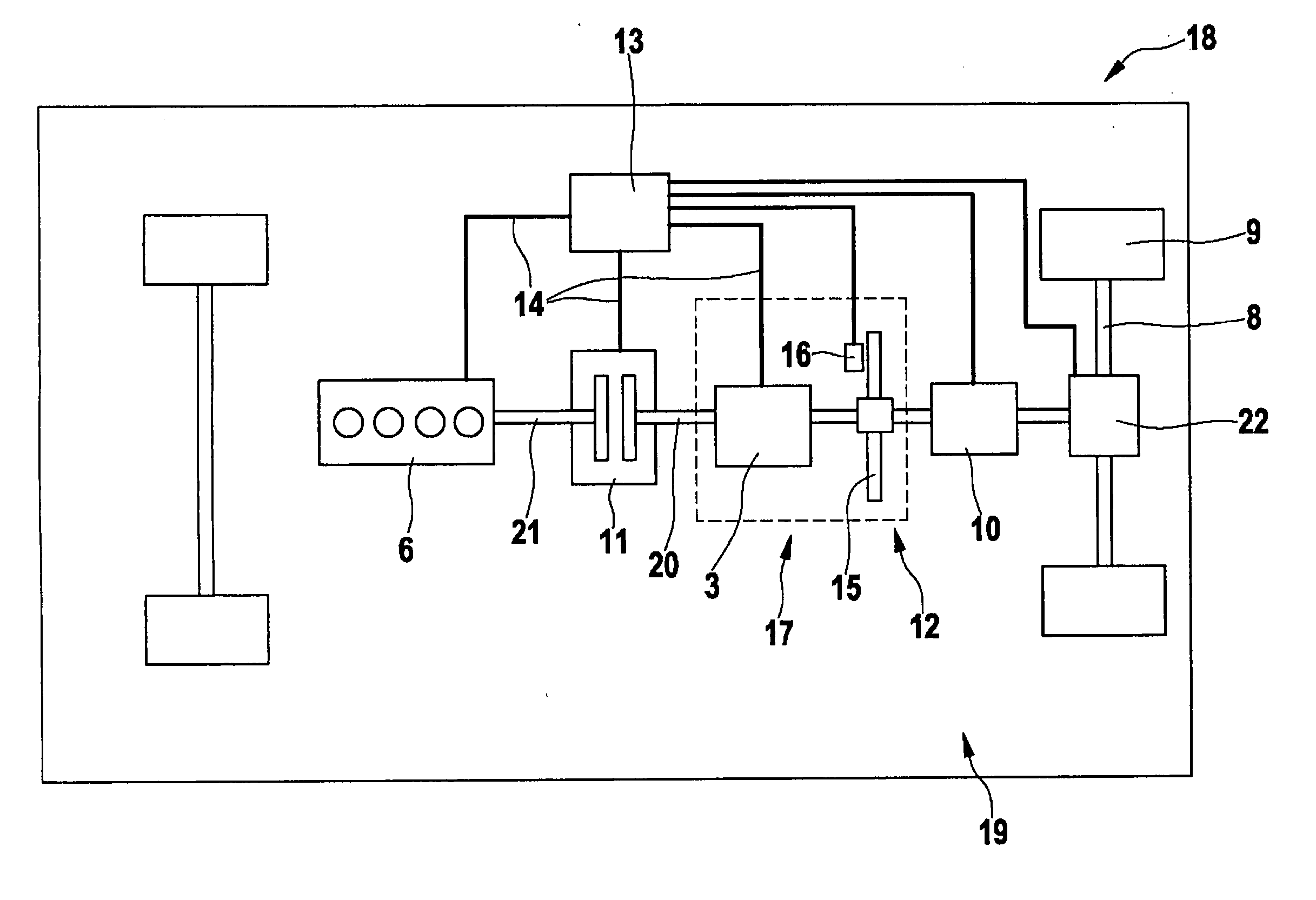
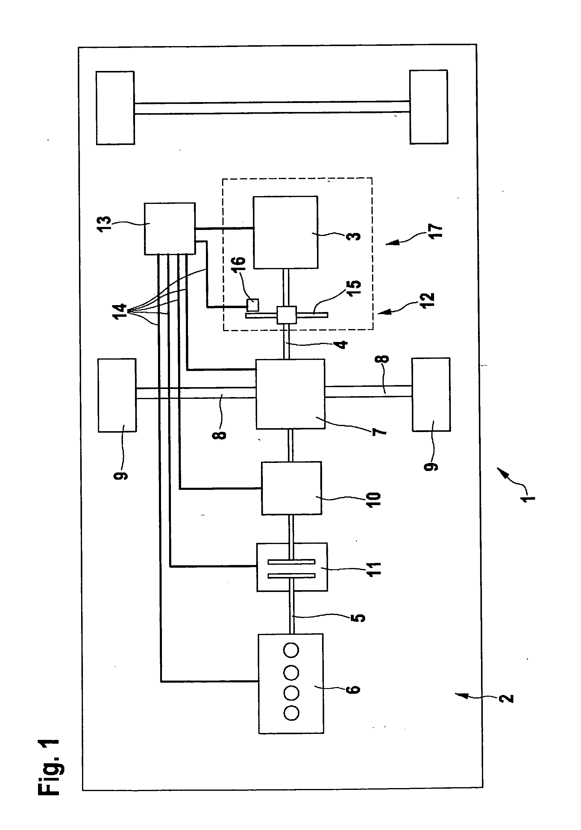
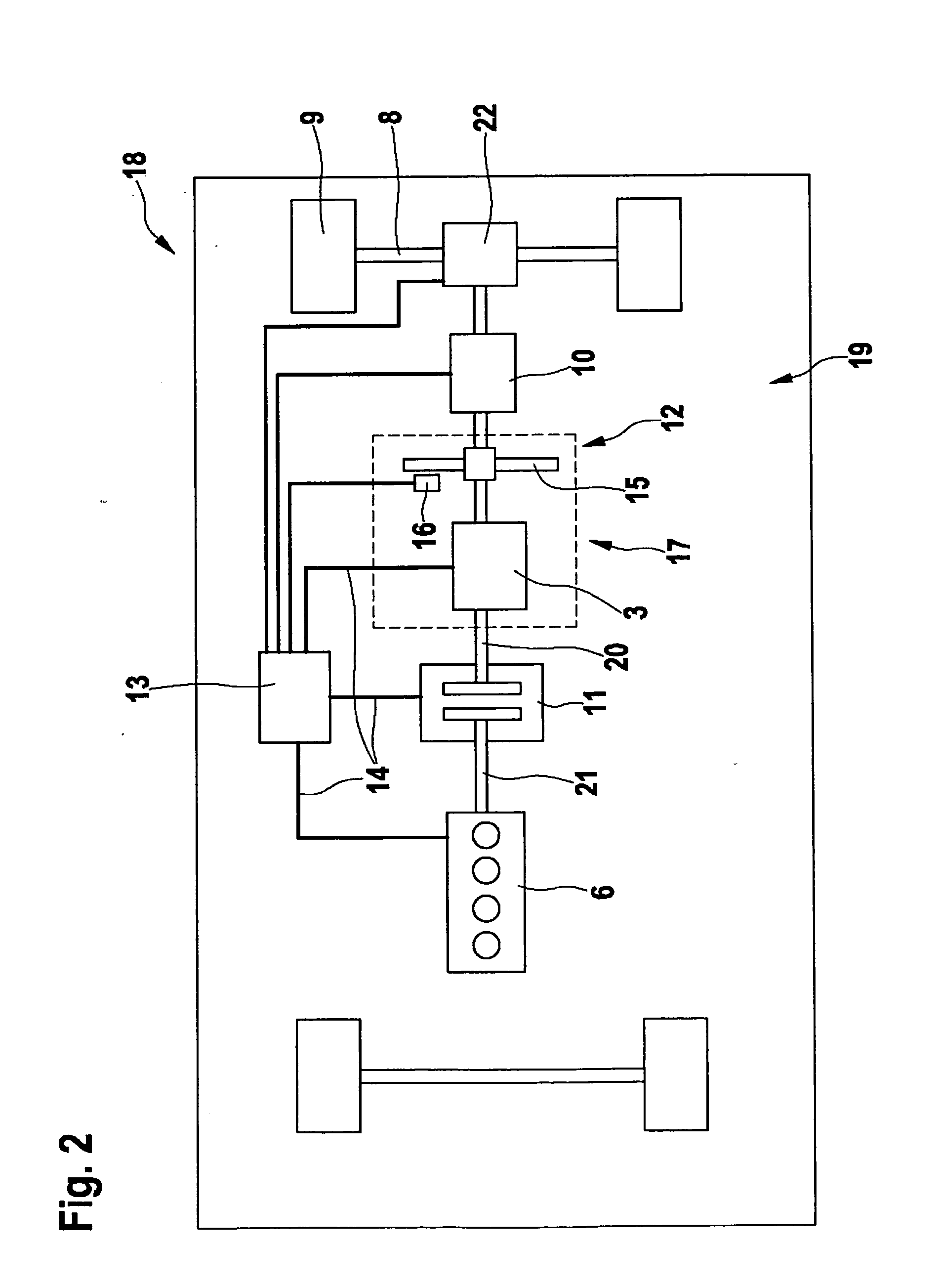
[0029]FIG. 1 shows a motor vehicle 1 having a hybrid drive 2 as the drive. Motor vehicle 1 and hybrid drive 2 are shown only schematically to illustrate the principle.

[0030]Hybrid drive 2 includes an electric machine 3 having a first drive shaft 4 and an internal combustion engine 6 having a second drive shaft 5. First drive shaft 4 is connected directly to electric machine 3, while second drive shaft 5 is connected directly to internal combustion engine 6. Both drive shafts 4, 5 are interlinked via a planetary gear 7. The shared drive power of internal combustion engine 6 and electric machine 3 (which may of course also be negative, for example, when the motor vehicle is in a recuperation mode) is supplied via planetary gear 7 to drive axle 8 on which wheels 9 are mounted. This design of a hybrid drive 2 is also known as so-called torque coupling. First drive shaft 4 and second drive shaft 5 are thus interlinked via planetary gear 7 at a fixed rotational speed ratio, which is prede...


PUM


Abstract

A hybrid drive system (2, 19) for a motor vehicle (1, 18) has an electric motor (3) and an internal combustion engine (6). The electric motor (3) and the internal combustion engine (6) are at least temporarily coupled (7, 10, 11) to each other at a fixed speed ratio. The speed of the hybrid drive system (2, 19) is sensed by a speed sensing device (12). The data obtained in said manner are used for at least partially controlling the electric motor (3) and the internal combustion engine (6).

Description

BACKGROUND OF THE INVENTION[0001]1. Field of the Invention[0002]The present invention relates to a hybrid drive system for a motor vehicle having at least one control system, at least one rotational speed detecting device, at least one electric machine and at least one internal combustion engine, and in which at least one electric machine and at least one internal combustion engine are linked together at least temporarily at a fixed rotational speed ratio. The present invention also relates to a method for operating at least one electric machine and at least one internal combustion engine, in which at least one of the electric machines and at least one of the internal combustion engines is designed and equipped in such a way that they are operated at least temporarily at a fixed rotational speed ratio to one another.[0003]2. Description of Related Art[0004]Against the background of rising crude oil prices and the developing changes in the earth's climate, there is an ever-growing de...

Claims


Application Information

Patent Timeline
IPC IPC(8): B60W20/00B60W10/06B60W10/08B60L50/16
CPCB60K6/48B60L2240/421B60L2240/441B60W10/06B60W10/08B60L2200/26B60W2510/0638B60W2510/081Y02T10/6221Y02T10/6286Y02T10/642B60W20/00Y02T10/62Y02T10/64B60W20/10
Inventor OTTO, STEPHAN
Owner ROBERT BOSCH GMBH
Learn More