
System and Method for the Treatment of Occluded Vessels

a technology for occluded vessels and catheters, applied in medical science, veterinary instruments, excision instruments, etc., can solve the problems of life-threatening medical conditions, difficulty for clinicians to control the amount of force applied at the distal end of guidewires, and failure of conventional protocols, so as to prevent life-threatening embolizations, improve the success of crossing the lesion, and minimize the risk of perforation

Inactive Publication Date: 2011-08-25
LJAHNICKY BORIS +1
View PDF15 Cites 67 Cited by
  • Summary
  • Abstract
  • Description
  • Claims
  • Application Information

AI Technical Summary

Benefits of technology

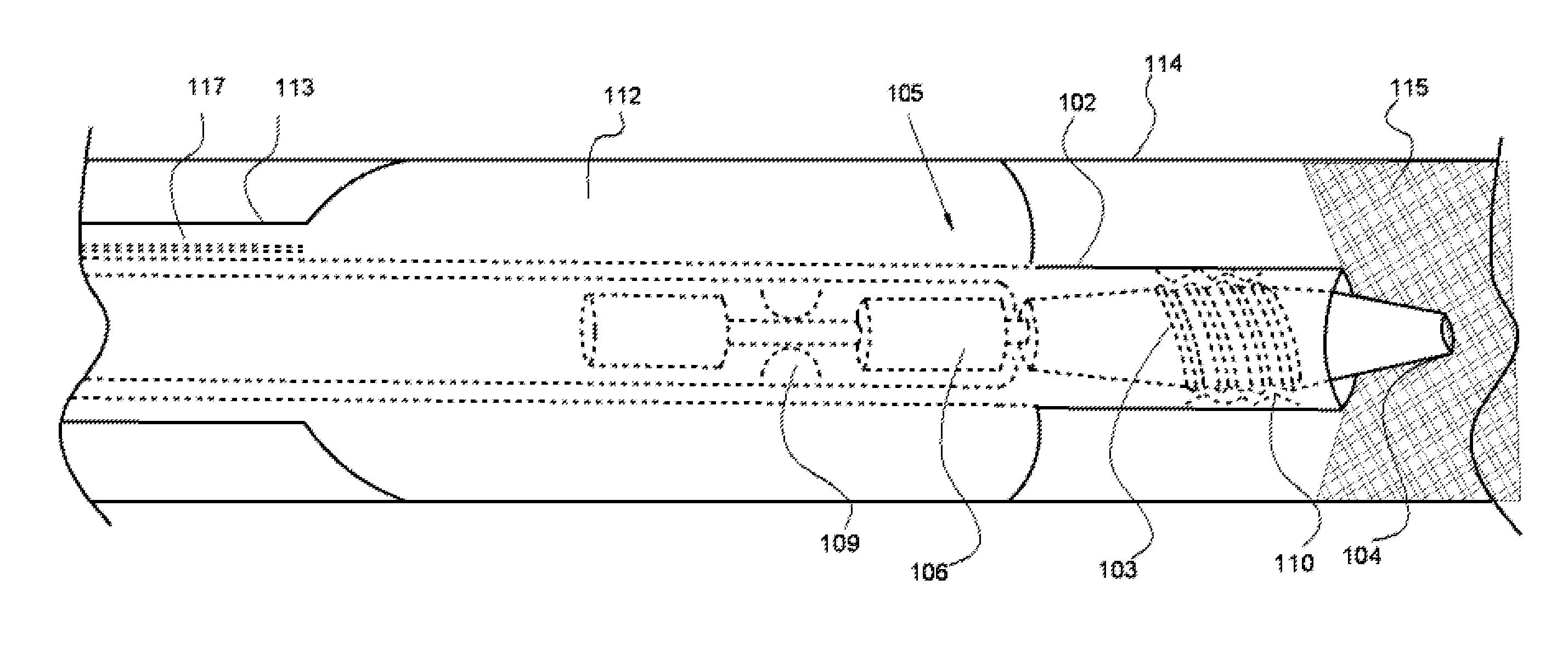
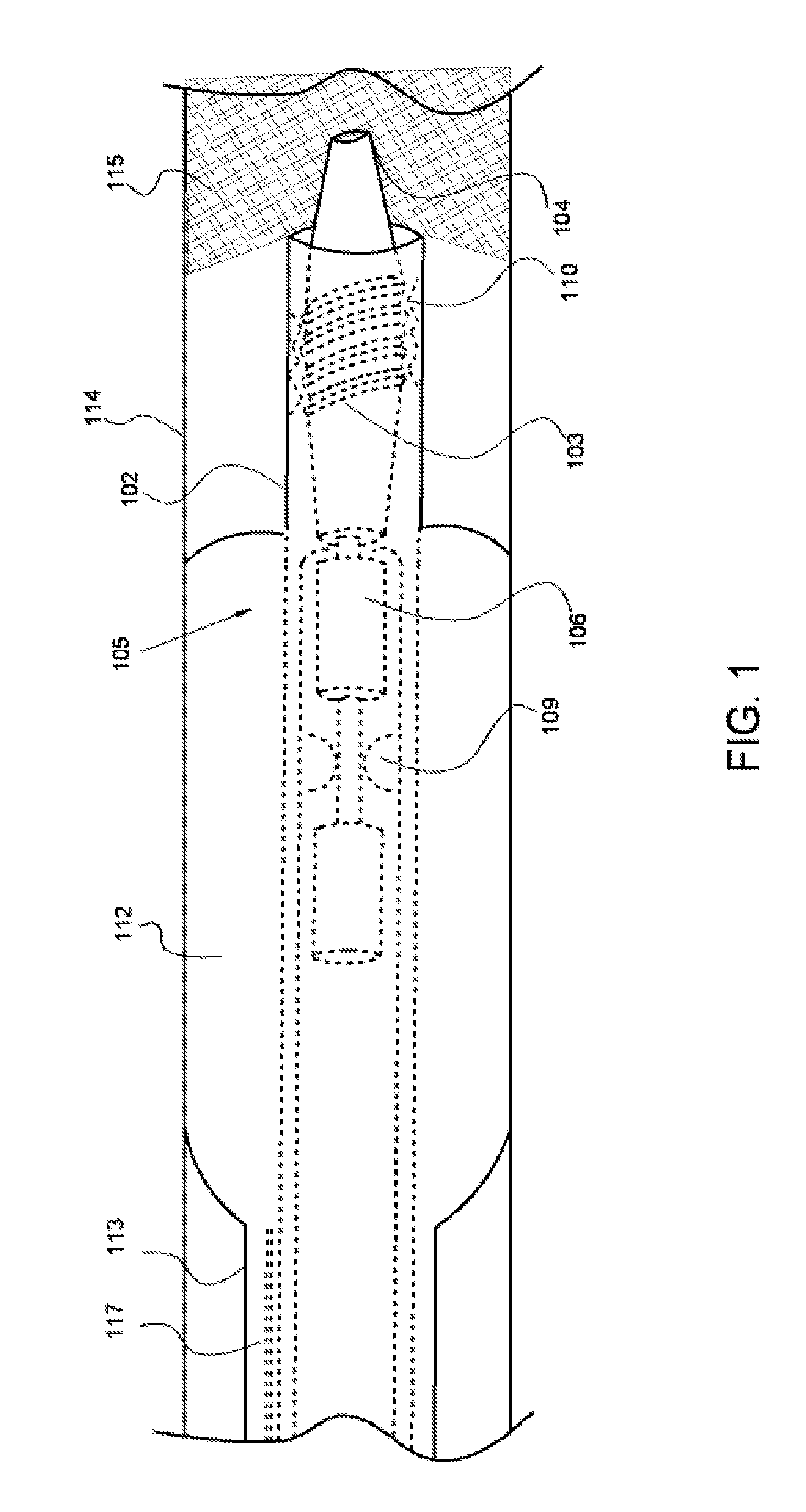
[0010]The present invention provides an occlusion treatment device that permits the clinician to apply a linear force on the proximal shaft to control a rotating guidewire tip's movement to within millimeters so as to effectively pierce a proximal fibrous cap. The device design enables treatment of all types of occlusions because of controlled maneuverability and safety within an artery. The occlusion treatment device also comprises a novel guidewire tip that has the ability to simultaneously cut and drill across a plaque formation. The system may also comprise a filtering system that simultaneously aspirates and filters out occlusion debris, and then returns clean blood to the patient, while providing an optional means to administer a therapeutic agent. This type of filtering system is especially efficacious in the use of arteries where there is a high occurrence of distal embolization, such as in the brain and kidneys.
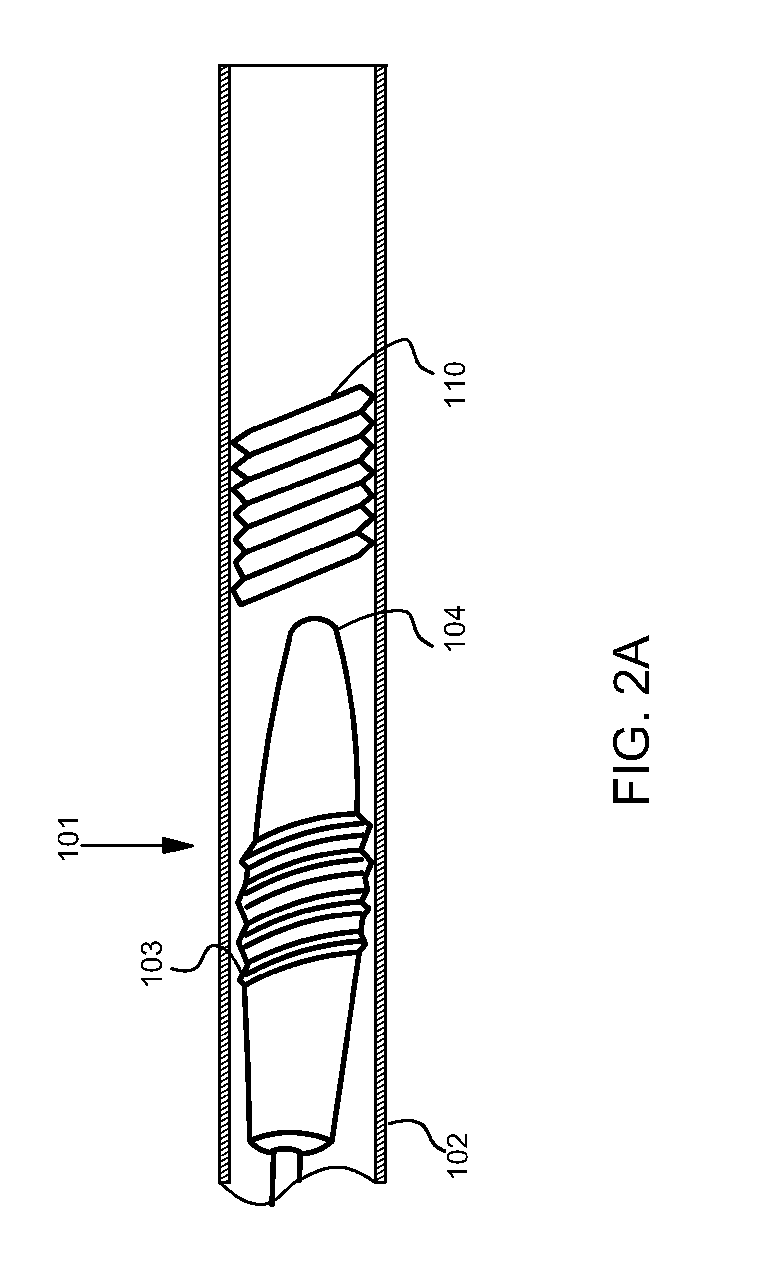
[0011]The present invention is accomplished by providing a method and a system for a catheter drilling device comprising a catheter system with two tubes and a guidewire with a rotating head. The catheter outer tube forms a lumen for inflation of a balloon to center the guidewire within the blood vessel. The catheter inner tube possesses either internal spiral threads or point slots to assist the guidewire movement. And the guidewire distal end comprises a tapered head with spiral helical windings and a cutting tip (optional), and a rotatable shaft with two securing rings. The rotatable shaft is encased in a proximal shaft, wherein when linear force is applied to the proximal shaft, the distal tip of the guidewire rotates and advances to a predetermined length; preferably about 2 millimeters, beyond the catheter distal end, while puncturing an occlusion cap. This device is especially efficacious at bifurcations because of the ability of the inflated balloon to safely center the rotating guidewire against the proximal cap so as to prevent it from bending and traveling into the adjoining lumen.

Problems solved by technology

Failure to remove the blockage can result in life threatening medical conditions, such as angina, hypertension, myocardial infarction, renal failure, and strokes.
More often than not, this conventional protocol is unsuccessful because of the guidewire's inability to penetrate and traverse the occlusion.
This maneuver makes it difficult for the clinician to control the amount of force applied at the guidewire distal end, and hence the direction and distance the guidewire tip travels within an artery.
Subsequently, there is an increased risk for damage to the vessel wall because of piercing or cutting by the guidewire tip.
These rotational devices have also not demonstrated successful use with stiff guidewires because of their resistance in transmitting a torque force from the proximal to the distal end of the wire.
These systems do not, though, provide for a mechanism to return the “cleaned” blood to a patient that was lost during the occlusion clearing and aspiration procedures, or to work within a rotatable drilling guidewire.

Method used


Image

  • System and Method for the Treatment of Occluded Vessels
  • System and Method for the Treatment of Occluded Vessels
  • System and Method for the Treatment of Occluded Vessels

Examples


Embodiment Construction

[0039]In the present invention the term “occlusion” refers to partial and total occlusion located within any artery. The present invention comprises a centering catheter with two tubes, one within another, and a guidewire with a rotating distal end. The guidewire may be solid or hollow. For example, in an alternative embodiment, the guidewire is hollow and houses a filtration system to aspirate debris and return clean blood to the occlusion site. The guidewire comprises a rotatable body and a proximal shaft. The rotatable body has two components: a distal rotating head and a proximal rotating shaft, wherein these components are of equal length and the rotating shaft resides within the proximal shaft.

[0040]Guidewires are used by medical clinicians for a variety of invasive procedures, and thus vary in size and stiffness in accordance with the type of procedure. The guidewire of the present invention may be about 120 centimeters to about 300 centimeters long, with a length of about 14...


PUM


Abstract

A system for treating an occlusive region of a blood vessel comprises: a catheter outer tube forming a lumen for inflation of a centering balloon; a catheter inner tube lined with either internal spiral threads or point slots to assist controlled guidewire movement; and a rotatable guidewire that may be solid or hollow. The guidewire comprises a rotatable body and a proximal shaft. The rotatable body has two components: a distal rotating head and a proximal rotating shaft, wherein these components are of equal length and the rotating shaft resides within the proximal shaft. Linear force applied to the proximal shaft will result in the rotational guidewire tip puncturing cutting through an occlusion. In an alternative embodiment, the guidewire rotatable body comprises two mechanical rings and a compression spring, wherein when the spring is released via depression of a button, the guidewire tip drills through an occlusion.

Description

PRIORITY CLAIMS TO RELATED PROVISIONAL APPLICATIONS[0001]The present application claims priority benefit under 35 U.S.C. §119(e) to U.S. Provisional Patent Application Ser. No. 61 / 307,887, filed Feb. 25, 2010, entitled “System and Method for Treatment of Occluded Vessels”, and Ser. No. 61 / 362,072, filed Jul. 7, 2010, entitled “Occlusion System with Spring Activated Guidewire Rotation”. The present application incorporates the foregoing disclosures herein by reference.TECHNICAL FIELD[0002]This invention relates generally to medical devices for treating vascular conditions. More specifically, the invention relates to a catheter incorporating a drilling guidewire.BACKGROUND OF THE INVENTION[0003]Occlusions develop in a patient's vascular system, e.g., brain, heart, kidneys and peripheral arteries, when atherosclerotic plaque formations block or significantly reduce the flow of blood. Occlusions lasting three or more months are termed “chronic total occlusions” (CTO). Failure to remove ...

Claims


Application Information

Patent Timeline
IPC IPC(8): A61B17/22
CPCA61B17/320758A61B2017/22044A61B2017/22094A61B2017/22079A61B2017/22068
Inventor LJAHNICKY, BORISAUERBACH, GUSTAVO
Owner LJAHNICKY BORIS
Learn More