Surface light source device
- Summary
- Abstract
- Description
- Claims
- Application Information
AI Technical Summary
Benefits of technology
Problems solved by technology
Method used
Image
Examples
first embodiment
[0135]A surface light source device according to a first embodiment of the present invention is described. FIG. 9 is a perspective view of a surface light source device 61 according to a first embodiment of the present invention, and FIG. 10 is a schematic sectional view thereof . The surface light source device 61 includes a point source of light 62 and a light guide plate 63. The point source of light 62 has one or a plurality of LEDs 62b incorporated therein, emitting white light. The LED(s) 62b is sealed in a transparent sealing resin 62c and, furthermore, the transparent sealing resin 62c is covered with a white resin 62d excluding a front portion. The front portion exposed from the white resin 62d of the transparent sealing resin 62c forms a light emission window 62a. This point source of light 62 is small compared with the width of the light guide plate 63 (dimensions in a depth direction on paper in FIG. 10), and is thus called a point source of light, as opposed to a cold-c...
modification example of first embodiment
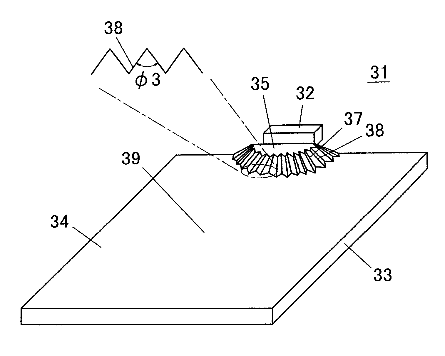
[0170]FIG. 14 is a perspective view of a surface light source device 76 according to a modification example of the first embodiment, and FIG. 15 is a partially-broken schematic sectional view of the surface light source device 76. Also, FIG. 16 is a plan view of a light introducing unit 35 of the surface light source device 76.
[0171]In the first embodiment, the auxiliary inclined surface 71 is provided adjacently to an inner perimeter side of the directivity conversion pattern 68. In this modification example, the auxiliary inclined surface 71 is provided adjacently to an outer perimeter side of the directivity conversion pattern 68. Also in this modification example, a relation between the half-width expected angle ξ and a ratio of leaked light is similar to that of the first embodiment. Note that also in this modification example, when a horizontal length from the inner perimeter edge to the outer perimeter edge of the auxiliary inclined surface 71 is taken as Δs, naturally,
ΔsT−t)...
second embodiment
[0173]In the surface light source device 61 of the first embodiment, the auxiliary inclined surface 71 is provided for the entire perimeter of the light introducing unit 35, that is, in a range of 180°, but is not necessarily required to be provided for the entire perimeter of the light introducing unit 35 and can be provided in a certain range including the front. This reason is described below.
[0174]When the light incident end face 66 of the light guide plate 63 is a flat surface, a directivity spread of incident light is narrowed due to the refractive index of the light guide plate 63. For example, when the material of the light guide plate 63 is polycarbonate resin, its refractive index n=1.59, and a light directivity spread of light entering the light incident end face 66 is ±90°, a directivity spread of light entering the inside of the light introducing unit 65 is
±α=±arcsin(1 / 1.59)=±39°.
Such a directivity spread inside the light introducing unit 65 is depicted in FIG. 17 and F...
PUM
 Abstract
Description
Claims
Application Information
 - R&D
- Intellectual Property
- Life Sciences
- Materials
- Tech Scout
- Unparalleled Data Quality
- Higher Quality Content
- 60% Fewer Hallucinations
Browse by: Latest US Patents, China's latest patents, Technical Efficacy Thesaurus, Application Domain, Technology Topic, Popular Technical Reports.
© 2025 PatSnap. All rights reserved.Legal|Privacy policy|Modern Slavery Act Transparency Statement|Sitemap|About US| Contact US: help@patsnap.com


