Display device, semiconductor device, and driving method thereof
a technology of semiconductor devices and drive methods, applied in the direction of pulse generators, pulse techniques, instruments, etc., can solve the problems of narrow drive frequency range of the drive frequency at which the semiconductor device can operate, difficult to lower the drive frequency of a semiconductor device such as a gate driver circuit, and loss of electric charge stored in the gate of the pull-up transistor as time passes, so as to reduce the drive frequency of the semiconductor device, widen the drive frequency range, and improve the operation of the semiconductor devi
- Summary
- Abstract
- Description
- Claims
- Application Information
AI Technical Summary
Benefits of technology
Problems solved by technology
Method used
Image
Examples
embodiment 1
[0031]In this embodiment, a circuit in a display device that is one embodiment of the present invention will be described.
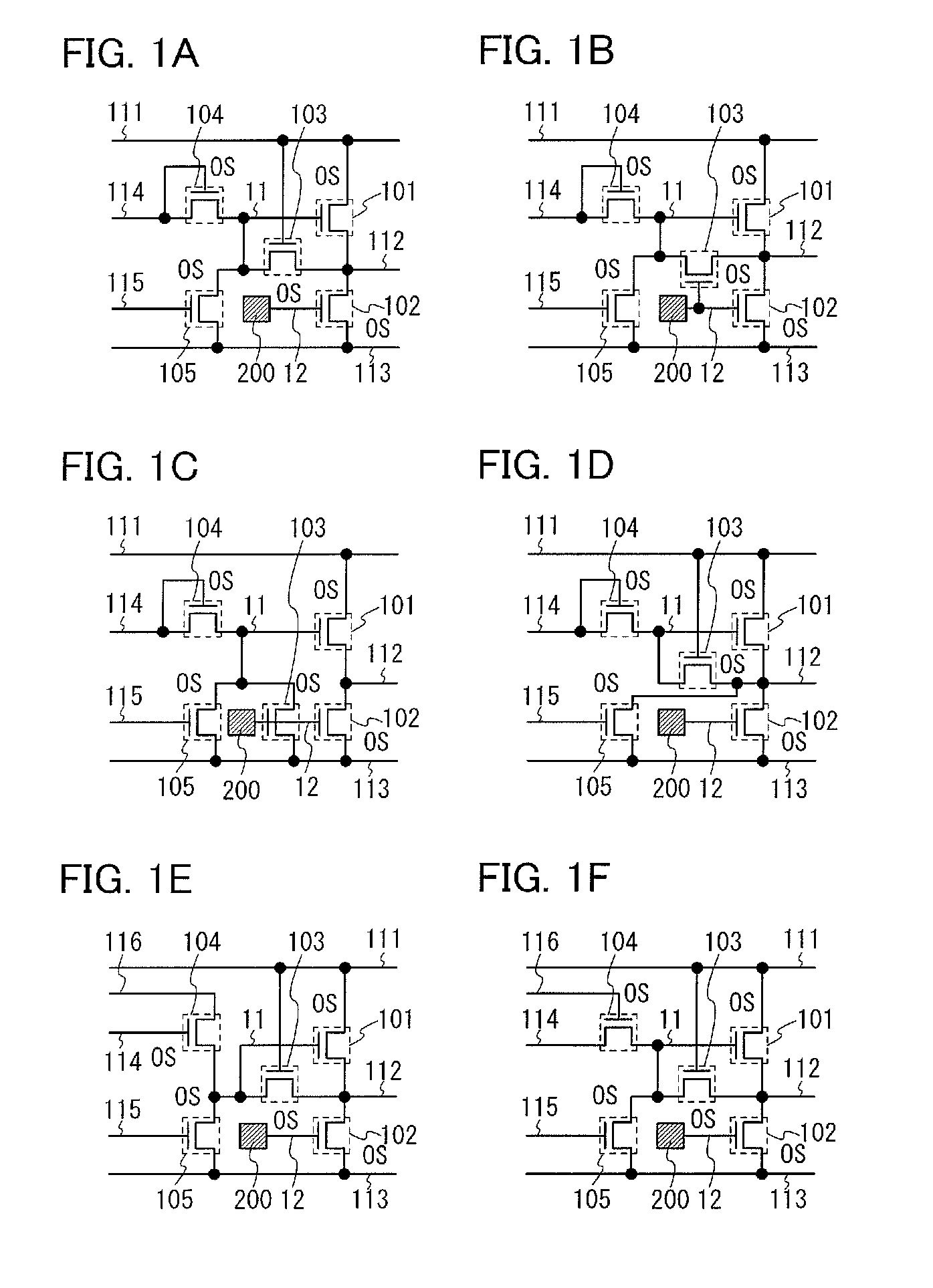
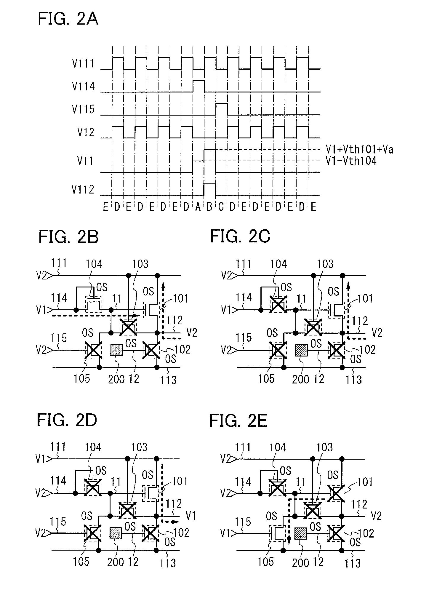
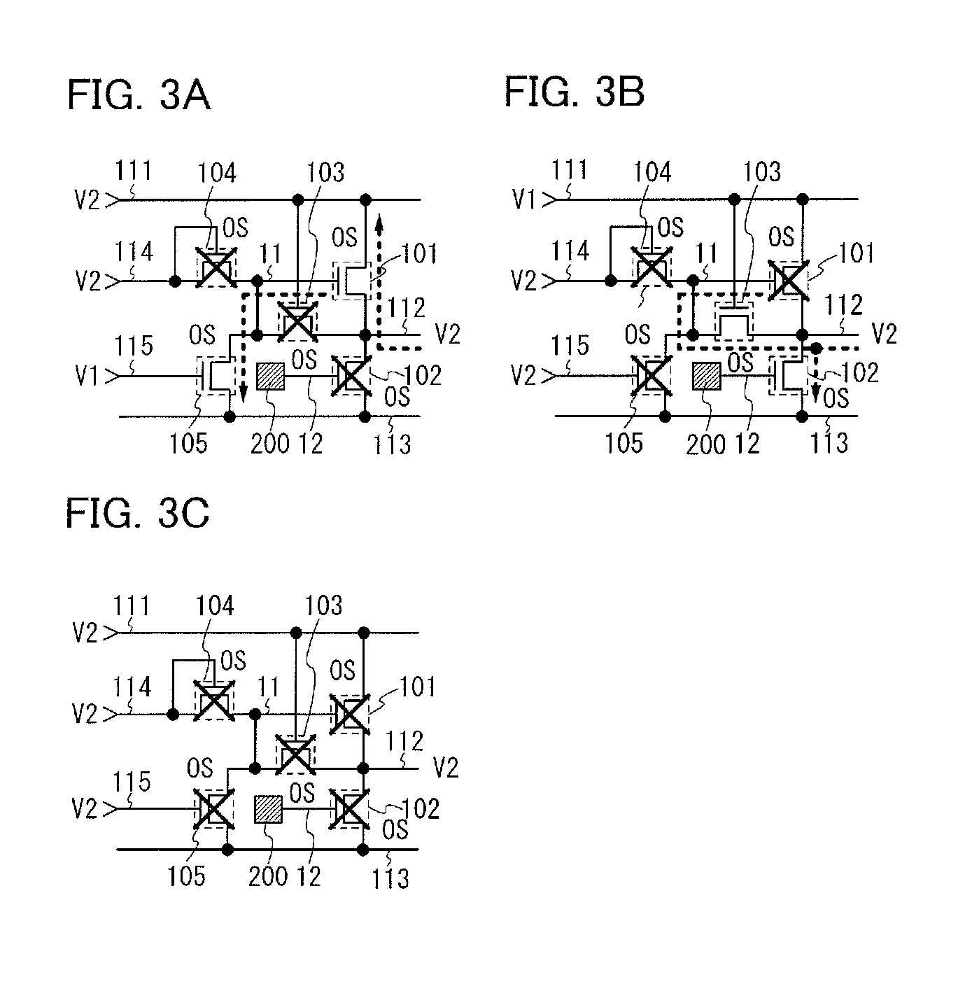
[0032]FIG. 1A shows an example of the configuration of a circuit including a transistor 101, a transistor 102, a transistor 103, a transistor 104, a transistor 105, and a circuit 200. The transistors included in the circuit shown in FIG. 1A are n-channel transistors. An n-channel transistor is turned on when a potential difference between a gate and a source is higher than the threshold voltage.
[0033]Note that the transistors included in the circuit shown in FIG. 1A can each have a semiconductor layer of an oxide semiconductor that is intrinsic (i-type) or substantially intrinsic, has an adequately lowered hydrogen concentration which makes the oxide semiconductor highly purified, and has an adequately low carrier concentration. This leads to improvement in the subthreshold swing of the transistor, a reduction in the off-state current of the transistor, improveme...
embodiment 2
[0081]In this embodiment, a shift register circuit in a display device which is one embodiment of the present invention will be described. A shift register circuit of this embodiment can include any of the circuits of Embodiment 1. Further, the shift register circuit of this embodiment can be used as a driver circuit of a display device, such as a gate driver circuit and / or a source driver circuit.
[0082]FIG. 8 shows an example of the configuration of a shift register circuit that includes N pieces of circuits 301 (circuits 301_1 to 301_N). Any of the circuits described in Embodiment 1 can be used as the circuit 301. FIG. 8 shows an example of the case where the circuit shown in FIG. 1A is used as the circuit 301.
[0083]Connections in the shift register circuit shown in FIG. 8 will be described. Connections in a circuit 301—i (i is included in 2 to N−1) will be described as an example. The circuit 301—i is connected to a line 311—i, a line 311_ / i−1, a line 311—i+1, either a line 312 o...
embodiment 3
[0092]In this embodiment, an example of a transistor included in the circuit of Embodiment 1 or 2 will be described. Specifically, examples of the structure of a transistor whose channel region is formed using an oxide semiconductor and fabrication steps thereof will be described.
[0093]As the oxide semiconductor, the following oxides can be used: an In—Sn—Ga—Zn—O-based oxide semiconductor that is an oxide of four metal elements; an In—Ga—Zn—O-based oxide semiconductor, an In—Sn—Zn—O-based oxide semiconductor, an In—Al—Zn—O-based oxide semiconductor, a Sn—Ga—Zn—O-based oxide semiconductor, an Al—Ga—Zn—O-based oxide semiconductor, or a Sn—Al—Zn—O-based oxide semiconductor that is an oxide of three metal elements; an In—Zn—O-based oxide semiconductor, a Sn—Zn—O-based oxide semiconductor, an Al—Zn—O-based oxide semiconductor, a Zn—Mg—O-based oxide semiconductor, a Sn—Mg—O-based oxide semiconductor, or an In—Mg—O-based oxide semiconductor that is an oxide of two metal elements; an In—O-b...
PUM
 Abstract
Description
Claims
Application Information
 - R&D
- Intellectual Property
- Life Sciences
- Materials
- Tech Scout
- Unparalleled Data Quality
- Higher Quality Content
- 60% Fewer Hallucinations
Browse by: Latest US Patents, China's latest patents, Technical Efficacy Thesaurus, Application Domain, Technology Topic, Popular Technical Reports.
© 2025 PatSnap. All rights reserved.Legal|Privacy policy|Modern Slavery Act Transparency Statement|Sitemap|About US| Contact US: help@patsnap.com


