
High-frequency coil pulling holes arrangement for producing multiple silicon cores

Inactive Publication Date: 2011-08-25
LUOYANG JINNUO MECHANICAL ENG
View PDF3 Cites 2 Cited by
  • Summary
  • Abstract
  • Description
  • Claims
  • Application Information

AI Technical Summary

Benefits of technology

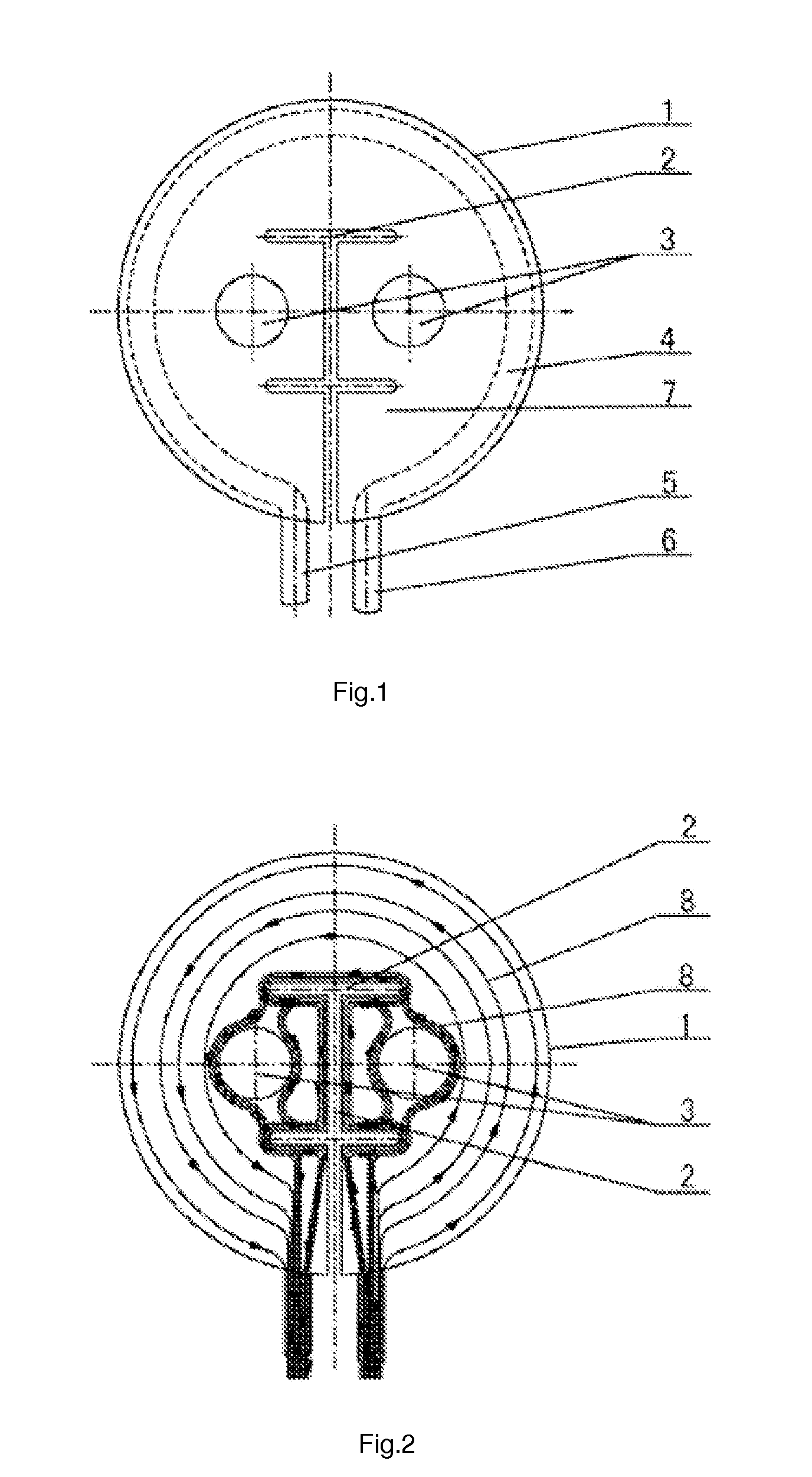
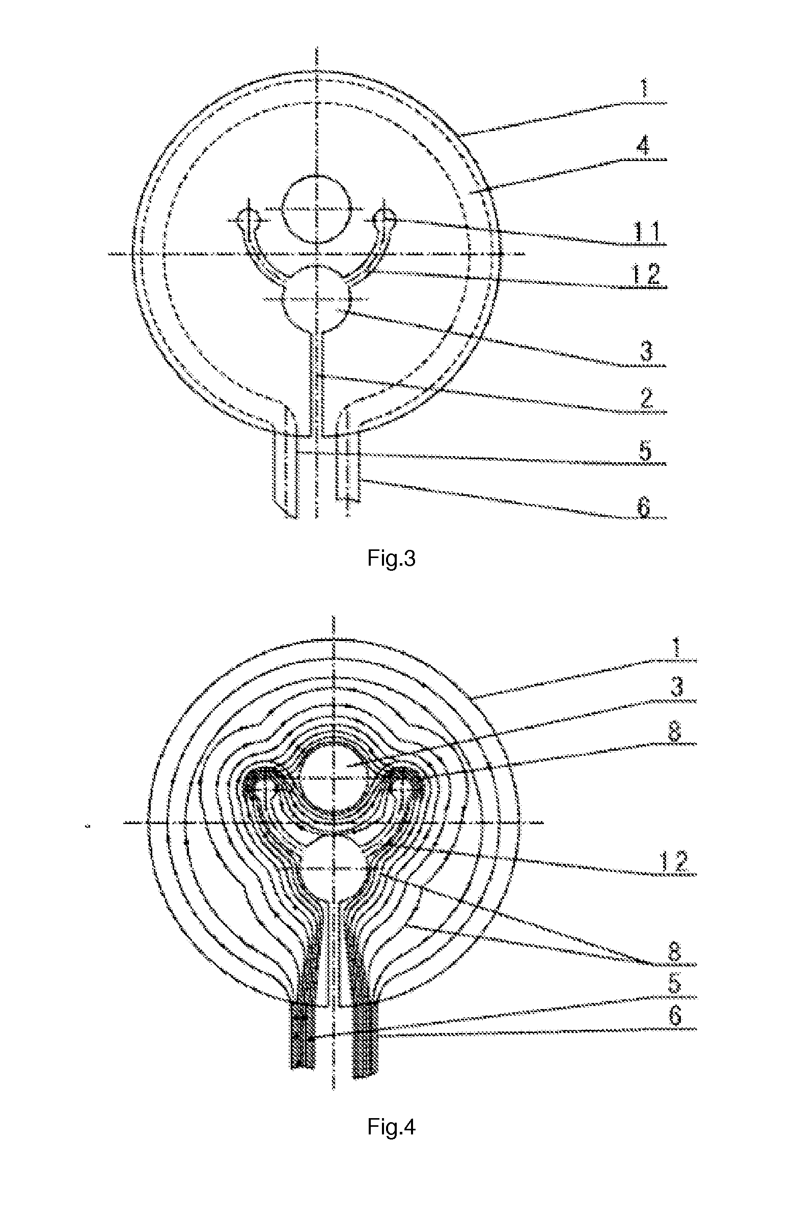
[0022]Aiming at effectively overcoming the problems, the invention provides a high-frequency coil pulling holes arrangement for producing multiple silicon cores. The running electric current can be made to spread generally uniformly around each said pulling hole by the diversion effect of diffluent trough or diffluent trough and subsidiary electric current guiding holes by means of changing the positions of diffluent trough and assisted by said “C” shape diffluent trough and subsidiary electric current guiding holes, and alternatively by means of providing interconnected diffluent trough between two pulling holes to form barbell-like part between pulling holes at the outer end of radial diffluent troughs. Because the electric current can more uniformly spread around each pulling hole assisted by diffluent trough, it is accomplished that the current is uniformly spread around pulling holes and consequently the appearance of low quality products can be diminished.
[0038]By adopting the technical scheme, the invention has the following advantages:
[0039]The high-frequency coil pulling holes arrangement for producing multiple silicon cores of the invention, wherein the diffluent troughs are radially arranged among the pulling holes; or the two sides of pulling holes are provided with C-shaped diffluent troughs and assisted by subsidiary electric current guiding holes; or the two sides of the pulling holes are respectively provided with short grooves; or the communicated diffluent troughs are arranged between every two pulling holes to form into a barbell-like part at the outer end of radial diffluent troughs for pulling 2-8 and 13 or 16 or 19 or 22 silicon cores. Because the running electric current can be made to spread generally uniformly around each said pulling hole by the diversion effect of diffluent trough or diffluent trough and subsidiary electric current guiding holes, and the electric current can more uniformly spread around each pulling hole under the assist of the diffluent troughs, it is accomplished that the current is uniformly spread around the pulling holes, consequently the appearance of low quality products can be diminished, the energy use ratio is improved, and the production cost and the defective percentage are reduced. The invention can evenly heat, saves a great deal of energy, reduces the equipment investment and labor aggregate cost, etc.

Problems solved by technology

As the high-frequency coils disclosed in the patents have no reasonable configuration, the uneven thickness of the seed crystal can be existed if multiple silicon cores are wanted to be produced simultaneously, so that it is impossible for simultaneously producing more than ten seed crystals with the high-frequency coils disclosed in the patents.

Method used


Image

  • High-frequency coil pulling holes arrangement for producing multiple silicon cores
  • High-frequency coil pulling holes arrangement for producing multiple silicon cores
  • High-frequency coil pulling holes arrangement for producing multiple silicon cores

Examples


Embodiment Construction

[0073]Referring to FIGS. 1 to 33, the invention comprises the following embodiments as detailed below.

[0074]Referring to the embodiment of FIG. 31, FIG. 32 and FIG. 33, FIGS. 1-30 are common to all embodiments. One side of a high-frequency coil 1 is provided with a current transmitting and cooling water transmitting cropper pipe A 5 and a current transmitting and cooling water transmitting cropper pipe B 6, which are adjacent to each other; inward-extended diffluent troughs 2 are arranged between the adjacent current transmitting and cooling water transmitting cropper pipe A 5 and the current transmitting and cooling water transmitting cropper pipe B 6; the upper surface 9 of the high-frequency coil 1 is an inclined plane which is inwards sunken to the center position; the lower surface 10 of the high-frequency coil 1 is provided with a middle sunken circular step; a cooling water channel 4 is buried circularly in the outer edge surface of the high-frequency coil 1; and the two ends...


PUM


Abstract

A high-frequency coil pulling holes arrangement for producing multiple silicon cores in the technical field of high-frequency coil is provided. The running electric current can be made to spread generally uniformly around each pulling hole by the diversion effect of diffluent trough or diffluent trough and subsidiary electric current guiding holes by means of changing the positions of diffluent trough and assisted by C-shaped diffluent trough and subsidiary electric current guiding holes, and alternatively by means of providing interconnected diffluent trough between two pulling holes to form barbell-like part between pulling holes at the outer end of radial diffluent troughs. Because the electric current can more uniformly spread around each pulling hole assisted by diffluent trough, it is accomplished that the current is uniformly spread around pulling holes and consequently the appearance of low quality products can be diminished.

Description

BACKGROUND OF THE INVENTION[0001]1. Field of the Invention[0002]The invention relates to high-frequency coils, and more particularly to a structure which can simultaneously produce multiple silicon cores or the crystalline materials by leading electric current to be evenly spread around pulling holes and silicon cores or the other crystalline materials to be evenly heated through the electric current, and particularly to a high-frequency coil pulling holes arrangement for producing multiple silicon cores or crystalline materials by leading the electric current to be evenly spread.[0003]2. Description of Related Art[0004]It is well known that with the gradual exhaustion of the non-renewable energy resources, the development and the use of the new energy resources such as the solar energy and the like have become a major trend. The polycrystalline silicon is a main material for producing the solar battery, the demand of the polycrystalline silicon of every country in the world is incr...

Claims


Application Information

Patent Timeline
IPC IPC(8): H05B6/36
CPCC30B29/06C30B13/20
Inventor LIU, CHAOXUAN
Owner LUOYANG JINNUO MECHANICAL ENG
Learn More