
End weighted mower blade

Inactive Publication Date: 2011-08-25
DAFFIN III CHARLES ERNEST
View PDF33 Cites 1 Cited by
  • Summary
  • Abstract
  • Description
  • Claims
  • Application Information

AI Technical Summary

Benefits of technology

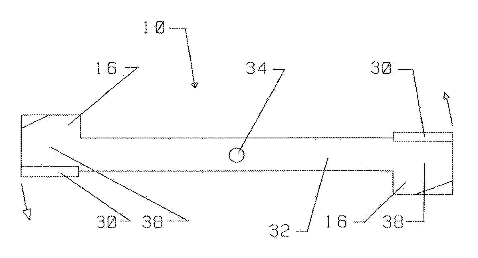
[0007]In accordance with the present invention, there is provides a mower blade with the most mass or weight on the outer, cutting edge. It is just that simple. Instead of having the blade mass relatively constant throughout the length, center pivot to outside cutting end, shift more mass to the outside. Leaving less mass or weight at the center pivot. Will work for any mower blade or any other rotating cutting blade. Shifting the most mass to the outer edge, creating a substantial weight difference between the center and the outer edges, will increase the kinetic energy of the outer cutting edge. Giving the mower more cutting power and increasing the useful life of the blade. Most all individual mowers, mow at a constant speed. At the mowing RPM the mower blade is spinning at a constant RPM. The velocity of the outside cutting edge is always moving at the same velocity or speed. So without increasing the blade speed, in order to generate more cutting power, this invention creates more mass or weight at the outter cutting edge to generate more power. “kinetic energy is a measure of work (or damage) that something can do if it collides with something else. The larger the speed and / or the larger the mass, the larger the kinetic energy, and thus the greater the impact” nmsea.org. E−Kinetic=½ mass×velocity×velocity. And as previously mentioned, added mass at the outer end, the cutting edge, gives the blade more damage power and a longer efficient cutting life. There will be less percentage of mass or weight loss at the outer blade end.

Problems solved by technology

And as previously mentioned, added mass at the outer end, the cutting edge, gives the blade more damage power and a longer efficient cutting life.

Method used


Image

  • End weighted mower blade
  • End weighted mower blade
  • End weighted mower blade

Examples


Embodiment Construction

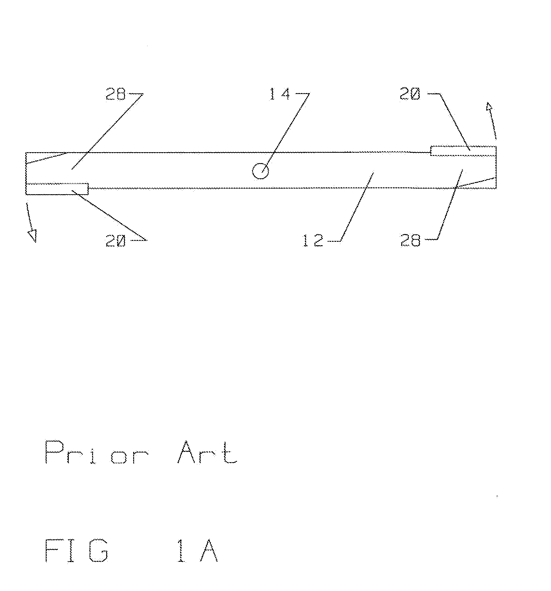
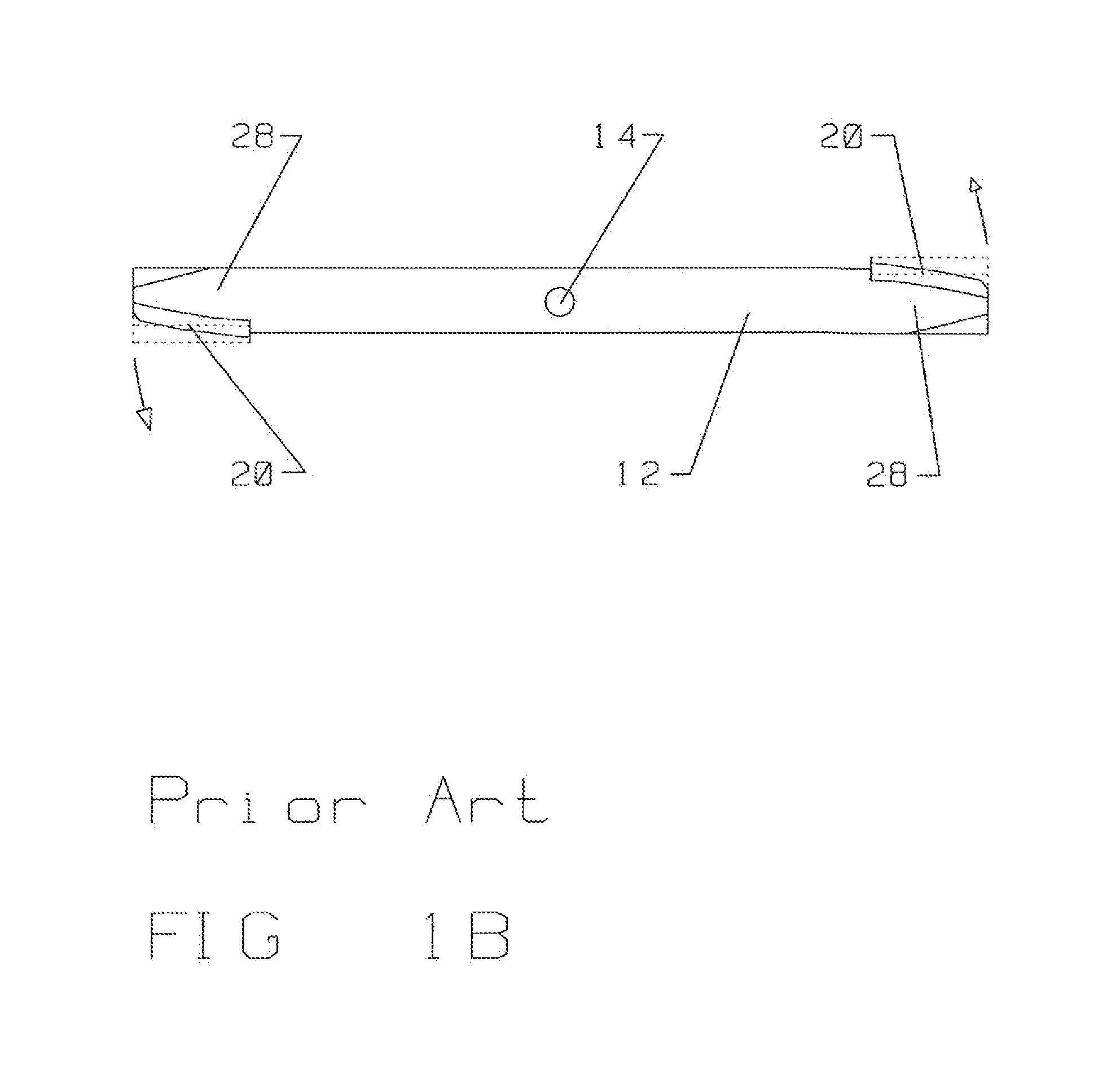
[0014]FIG. 1 is a top plan view. Showing a standard mower blade at the top two, and the invention proposed at the bottom two. The bottom two blades having more mass at the outside cutting edge 20. The top two blades are typical mower blades, showing the center hole of rotation 14, the cutting edge 20 on the outer end 28. The standard blade 12 has basically the same size througout. Same thickness and width from center hole of rotation 14 to outer end 28 at the cutting edge 20. Some blades do have minor shape changes but not enough to be relevant to a substantial increase in mass on the outer end 28. The second blade down from the top is the same standard blade 12 with a worn edge 22. The worn edge 22 has reduced the mass on the outer cutting edge 20, causing a significant decrease in cutting potential. Because of less mass, the energy delivered is now less, which equals less damage to the object being cut. This kind of wear on a standard blade 12 could reduce its cutting efficiency b...


PUM


Abstract

A mower blade generally comprised of a rotor which connects to the mower at an attachment point and at least one outer end of the rotor, wherein the outer end or ends of the rotor are heavier than the rotor proximate the attachment point. The added weight to the outer end can be by way of an extension or an end section.

Description

FIELD OF THE INVENTION[0001]The present invention relates to mower blades and, more particulary, to the weight or mass distribution of the blades center compared to the blades outter most end.BACKGROUND OF THE INVENTION[0002]When mower blades are new, they cut just fine. But after wear from use, they start loosing mass or weight on the outer end. Also from repeated sharpening the blade looses mass on the cutting edge, which is the outer most end of the blade. As the blade end loses such mass or weight, it becomes less efficient at cutting and eventually has to be replaced with a new, unworn, blade. What is needed is a blade that does not loose its cutting efficiency after wear from use and sharpening. And such remedy would also increase the cutting power of the blade.[0003]Am not aware of any solutions to date[0004]It would be advantageous to provide a mower blade that can wear and continue to efficiently cut.[0005]It would also be advantageous to provide a mower blade that after co...

Claims


Application Information

Patent Timeline
IPC IPC(8): A01D34/13
CPCA01D34/73
Inventor DAFFIN, III, CHARLES ERNEST
Owner DAFFIN III CHARLES ERNEST
Learn More