Eureka AIR delivers breakthrough ideas for toughest innovation challenges, trusted by R&D personnel around the world.

Lighting unit with heat-dissipating chimney

a technology of heat dissipation chimney and light unit, which is applied in the direction of lighting and heating apparatus, semiconductor devices for light sources, and light support devices

Active Publication Date: 2011-08-18
SATCO PRODS
View PDF30 Cites 173 Cited by
  • Summary
  • Abstract
  • Description
  • Claims
  • Application Information

AI Technical Summary

Benefits of technology

[0012]Aspects of the invention may provide a novel lighting unit that avoids the problems of the prior art.
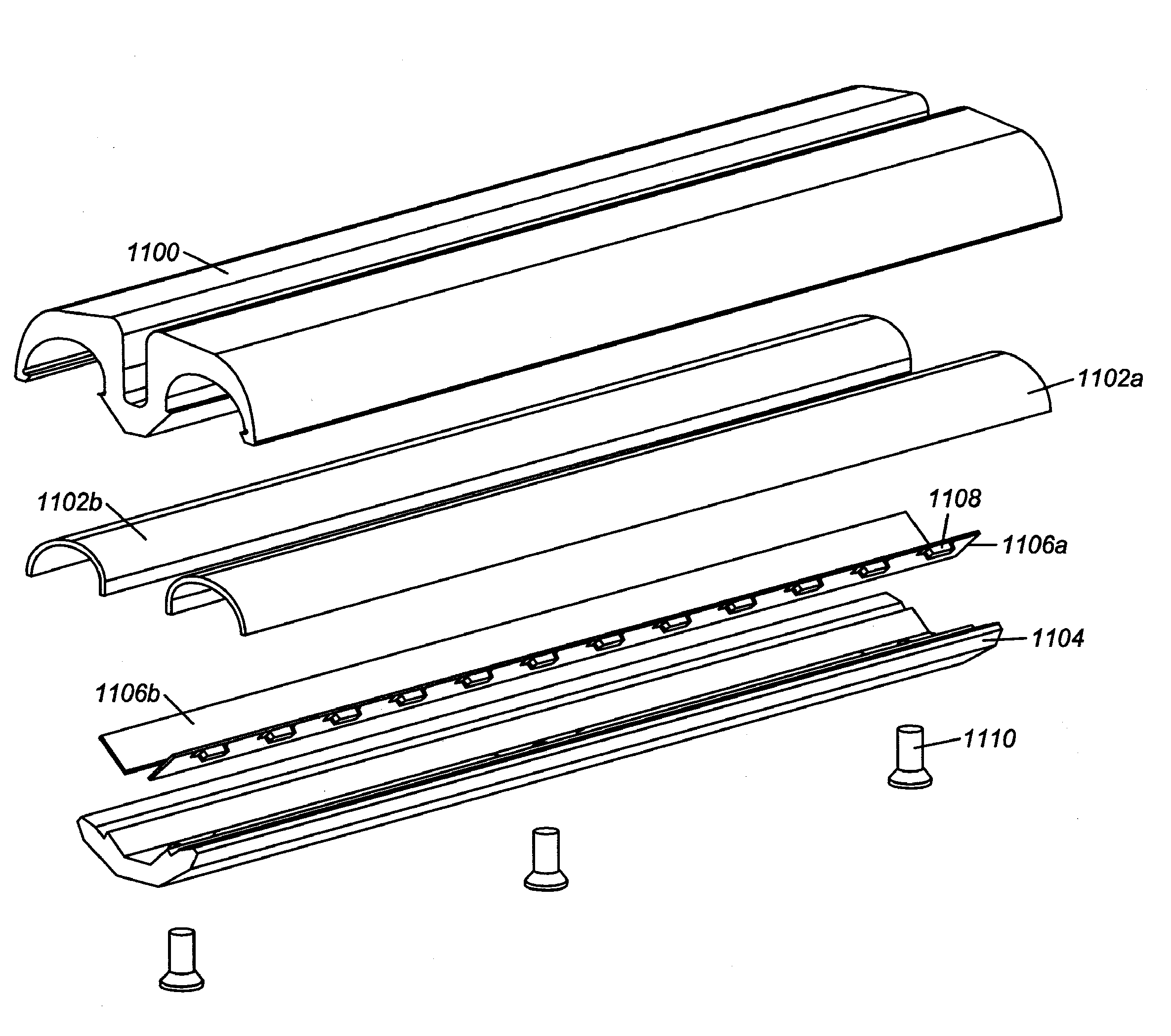
[0013]The invention may also provide a novel lighting unit having one or more lighting strips, each lighting strip having a heat dissipating support structure, a plurality of light emitting elements, and a base reflector with a luminescent material disposed thereon. The luminescent material is excited by at least some of the light emitting elements and emits light of a longer wavelength. The base reflector can be configured to direct light out of the lighting unit or to one or more optical elements that can be used to refract, reflect, and / or diffract the light to achieve a desired distribution of light.

Problems solved by technology

Fluorescent lamps fail under excessive vibration, require a high operating voltage, consume a large amount of power, generally have poor color quality, they cannot be started in cold temperatures or in humid environments, they emit light in 360 degrees about the length of the lamp such that much light is lost in reflection, and they contain mercury, making the lamps difficult to dispose of and hazardous to human health and the environment.
The LEDs appear as point sources along the length of the lamp, so light is harsh, not uniform or well distributed, and limited to the color quality and consistency of the LED sources.
A refracting or scattering cover can be used to diffuse the light for a more uniform appearance, but this either adds significant cost (for a highly efficient diffuser) or loss of lamp efficiency.
Furthermore, LEDs generate significant amounts of heat which reduces the lifetime and efficiency of the LED devices.
In these lamps, the LED devices are enclosed in a tubular bulb, further increasing the operating temperature due to the large amount of trapped heat.
Some lamps incorporate a horizontal heat sink, but such a heat sink, even with fins or grooves, is not very effective.
Largely due to heat management issues, these proposed fluorescent tube replacement lamps will have reduced system efficacy, reduced lumen maintenance, problems with color consistency over lifetime, and uncertain reliability.
Though this patent provides more uniform light, it requires a large amount of phosphor material to manufacture.
Phosphor material can be extremely expensive, thus preventing achieving the cost goals required for adoption of this technology.
Furthermore, though thermal issues are mitigated with the use of a remote phosphor, thermal management is not optimized and may result in reduced system efficacy, lumen maintenance issues, and uncertain reliability.

Method used


Image

  • Lighting unit with heat-dissipating chimney
  • Lighting unit with heat-dissipating chimney
  • Lighting unit with heat-dissipating chimney

Examples


examples

[0230]A lighting unit having one or more of the features described, such as a heat transfer chimney, was tested at multiple National Institute of Standards and Technology (NIST) traceable labs. The lighting unit had a heat dissipating support structure formed of aluminum, LEDs (e.g., NSSW208A surface mounted LEDs from Nichia Corp. of Tokushima, Japan) mounted on a PCB circuit board, a first optical element, and two second optical elements (e.g., which may have a reflective surface material such as WO-F33 high diffuse reflectance film from WhiteOptics LLC of Newark Del.). In one of the tests, a lighting unit had a luminescent material disposed on a second optical element (e.g., Intematix 05446 Eu doped silicate phosphor from Intematix Corp. of Fremont, Calif.). In another test, the lighting unit did not have the luminescent material.

[0231]Some measurements were taken in an integrating sphere. An LED drive current of 20 mA per LED was provided. The ambient temperature was 25 degrees C...


PUM

PropertyMeasurementUnit
Poweraaaaaaaaaa
Lengthaaaaaaaaaa
Electrical conductoraaaaaaaaaa

Abstract

The invention provides systems and methods for providing illumination. A lighting unit may have a support structure, and one or more light emitting elements supported by a circuit board contacting the support structure. A first optical element and a second optical element may be provided. A remote luminescent material may be provided on one or more optical elements. Light emitting elements configured to excite the luminescent material such as highly efficient light emitting diodes may be directed towards the luminescent material. The support structure may be a heat dissipating element, which may conduct heat from a heat source to a surface of the support structure. The heat dissipating element may have a passageway permitting the formation of a convection path to dissipate heat from the support structure. Such lighting units may be used to replace conventional fluorescent light tubes or other lighting devices, or may be provided as standalone lighting units.

Description

CROSS-REFERENCE[0001]This application claims the benefit of U.S. Provisional Application No. 61 / 338,268, filed Feb. 17, 2010, which application is incorporated herein by reference.BACKGROUND OF THE INVENTION[0002]Fluorescent lamps are widely used for lighting in commercial buildings, residential spaces, as well as on transit buses and in outdoor lighting. Fluorescent lighting provides some advantages, such as improved efficiency, over other lighting options such as incandescent lighting. However, there are several drawbacks. Fluorescent lamps fail under excessive vibration, require a high operating voltage, consume a large amount of power, generally have poor color quality, they cannot be started in cold temperatures or in humid environments, they emit light in 360 degrees about the length of the lamp such that much light is lost in reflection, and they contain mercury, making the lamps difficult to dispose of and hazardous to human health and the environment.[0003]Various solutions...

Claims


Application Information

Patent Timeline
IPC IPC(8): F21S4/00F21V9/40
CPCF21V7/22F21V9/16F21Y2103/003H05B41/02F21V13/08F21K9/10F21V7/00F21V13/02F21Y2101/02F21K9/20F21Y2103/10F21Y2115/10F21V9/30F21V7/28F21V13/14F21V5/04
Inventor BRETSCHNEIDER, ERICBERKOWITZ, ZACHSOSNICK, RANDALLPATTISON, LISAPATTISON, P. MORGAN
Owner SATCO PRODS
Why Eureka
Eureka Blog
Learn More