Method and system for processing an input three dimensional video signal

a three-dimensional video and input technology, applied in the field of methods and systems for processing three-dimensional video signals, to achieve the effect of reducing disadvantages

Inactive Publication Date: 2011-08-18
KONINKLIJKE PHILIPS ELECTRONICS NV
View PDF6 Cites 38 Cited by
  • Summary
  • Abstract
  • Description
  • Claims
  • Application Information

AI Technical Summary

Benefits of technology

[0006]It is a goal of the present invention to mitigate the disadvantages of having encoded the disparity relationship in stereo or multiview content for three dimensional displays when applying overlays.
[0007]This goal is achieved by a method of processing an input three dimensional video signal according to the present invention wherein the method comprises: determining a far disparity estimate indicative of the largest disparity value for the input three dimensional video signal and a near disparity estimate indicative of the smallest disparity value for a spatial region within the input three dimensional video signal, adapting the three dimensional video signal by shifting the input three dimensional video signal backwards by means of a disparity shift based on the far disparity estimate and generating an overlay within the spatial region for the shifted three dimensional video signal based on the near disparity estimate and the disparity shift. By making some of the disparity information (the far and near values) explicit (as opposed to the implicit information in the multi-view image data), explicit processing such as determining the amount of shift is made possible.
[0018]A positive disparity larger than eye distance corresponds to divergent eye lines, which are not physically interpretable. As a result positive disparity larger than eye distance may cause viewing discomfort. To avoid this it is possible to set the maximum disparity to an average eye distance, or to a value below the average distance. Preferably the maximum disparity is selected such that a safety margin is taken into account so as to maintain comfort for all viewers. Alternatively the maximum disparity may be a user defined value optionally upper bounded by the average eye distance. The latter is particularly advantageous as it allows for compensation in differences in eye distance between e.g. adults or children.

Problems solved by technology

However, as glasses may be considered inconvenient to the user, it is in many scenarios preferred to use autostereoscopic displays that use means at the display (such as lenticular lenses, or barriers) to separate views, and to send them in different directions where they individually may reach the user's eyes.
A problem associated with the delivery of stereo or multiview content comprising actual encoded views for display is that these images effectively fix the disparity relationship between the two or more respective views in an implicit manner.

Method used


Image

  • Method and system for processing an input three dimensional video signal
  • Method and system for processing an input three dimensional video signal
  • Method and system for processing an input three dimensional video signal

Examples


Embodiment Construction

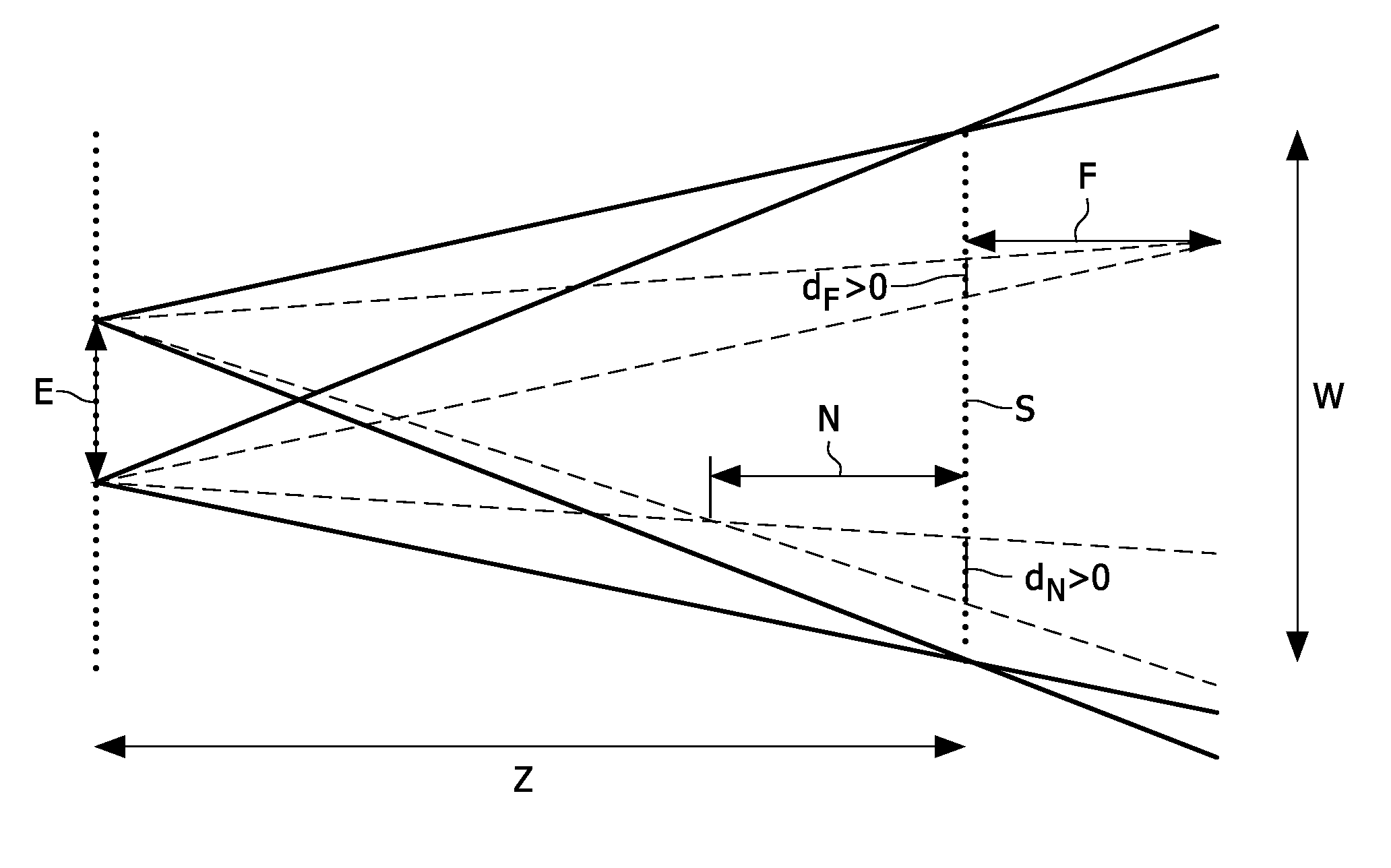
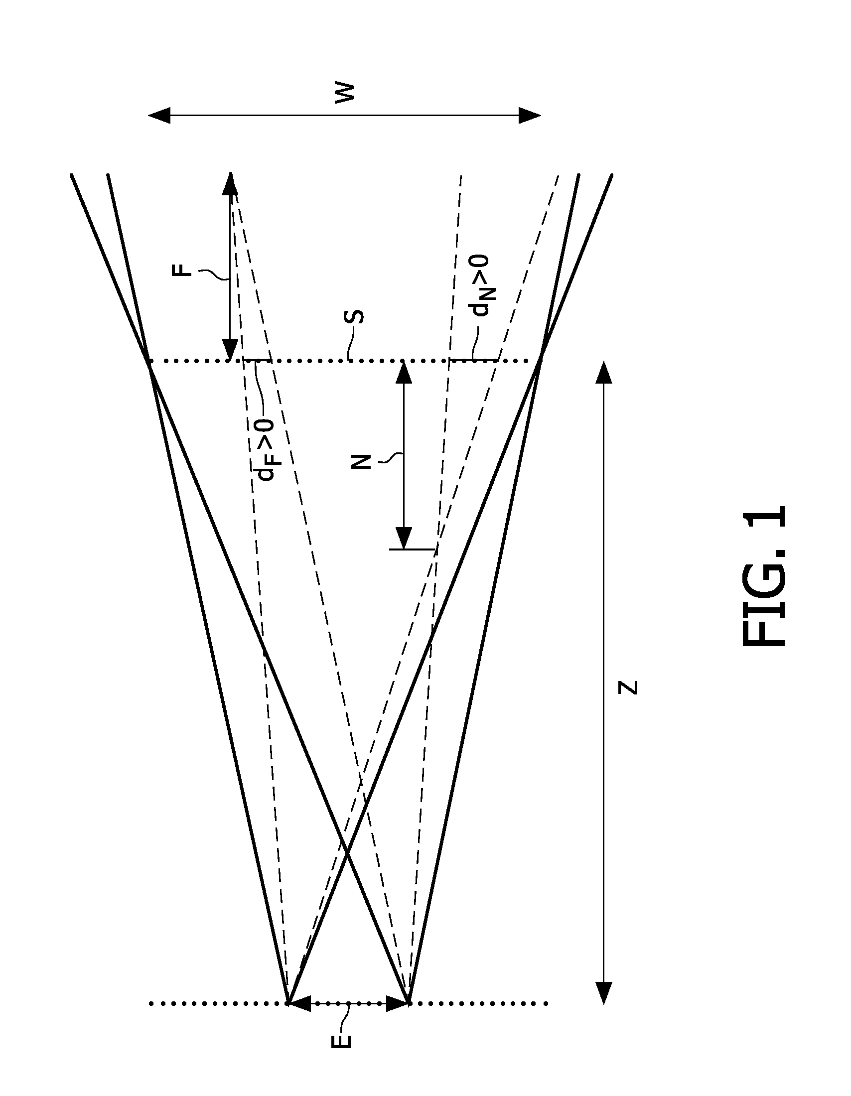
[0035]FIG. 1 illustrates several general concepts and parameters defining disparity. FIG. 1 shows two viewpoints located at the edges of the double arrow E, spaced apart by eye-distance E. At a viewing distance Z, a screen S, represented by a dotted line, is located which is used for displaying three dimensional information. Such a screen in practice may be e.g. a time or spectrum sequential display that alternatively provides an eye of an observer wearing appropriate eye-wear with appropriate image information for the respective view point. The screen S here is placed at zero disparity, and W indicates the width of the screen. N (near) represents the maximum perceived depth in front of the screen S. Likewise F (far) represents the maximum perceived depth behind the screen S. The line dN represents the perceived disparity of an object located at N in front of the screen S, the disparity value dN here is negative, also referred to as crossed disparity and can be expressed as:

dN=N E / (...


PUM


Abstract

The invention relates to a system and method of processing an input three dimensional video signal comprising multiple views, the method comprising: determining a far disparity estimate indicative of the largest disparity value for the input three dimensional video signal, a near disparity estimate indicative of the smallest disparity value for a spatial region within the input three dimensional video signal, adapting the input three dimensional video signal by shifting the input three dimensional video signal backwards by means of a disparity shift based on the far disparity estimate and generating an overlay within the spatial region for the shifted three dimensional video signal based on the near disparity estimate and the disparity shift. The invention further relates to a computer program product implementing a method according to the present invention.

Description

FIELD OF THE INVENTION[0001]The invention relates to a method and a system for processing an input three dimensional video signal as well as to a computer program product for implementing the method according to the invention.BACKGROUND OF THE INVENTION[0002]Display devices suitable for displaying three-dimensional images are receiving an increasing interest in research. In addition substantial research is undertaken in order to establish how to provide end-users with a satisfying, high quality viewing experience.[0003]Three dimensional (3D) displays add a third dimension to the viewing experience by providing both eyes of a viewer with different views of the scene being watched. This can be achieved by having the user wear glasses to separate two views that are displayed. However, as glasses may be considered inconvenient to the user, it is in many scenarios preferred to use autostereoscopic displays that use means at the display (such as lenticular lenses, or barriers) to separate...

Claims


Application Information

Patent Timeline
Patent Type & Authority Applications(United States)
IPC IPC(8): H04N13/00H04N13/128
CPCH04N13/0018H04N13/007H04N13/0022H04N13/128H04N13/183H04N13/122H04N13/00
Inventor BARENBRUG, BART G.B.VAN DER HEIJDEN, GERARDUS W.T.SWILLENS, PETER J.L.A.
Owner KONINKLIJKE PHILIPS ELECTRONICS NV
Why Eureka
Try Eureka