
Environmental control system for precision airborne payloads

a control system and precision airborne technology, applied in vehicle heating/cooling devices, process and machine control, navigation instruments, etc., can solve the problems of affecting the performance of optical system components, consuming a large amount of electrical power and critical volume aboard aircraft, and acm and vcm machines each weigh approximately 100 pounds, so as to achieve reliable temperature and humidity control

Active Publication Date: 2011-08-11
BAE SYST INFORMATION & ELECTRONICS SYST INTERGRATION INC
View PDF28 Cites 17 Cited by
  • Summary
  • Abstract
  • Description
  • Claims
  • Application Information

AI Technical Summary

Benefits of technology

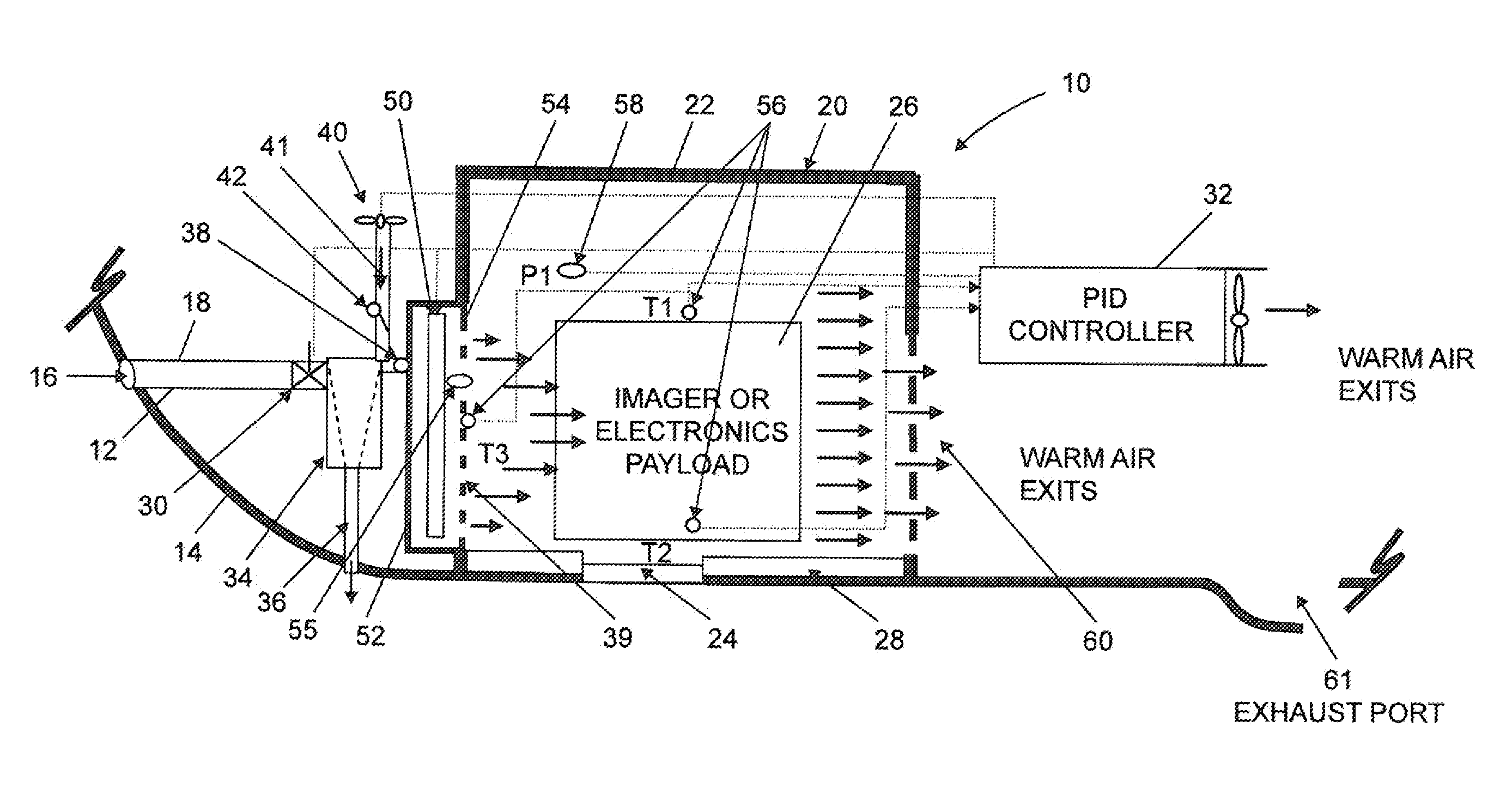
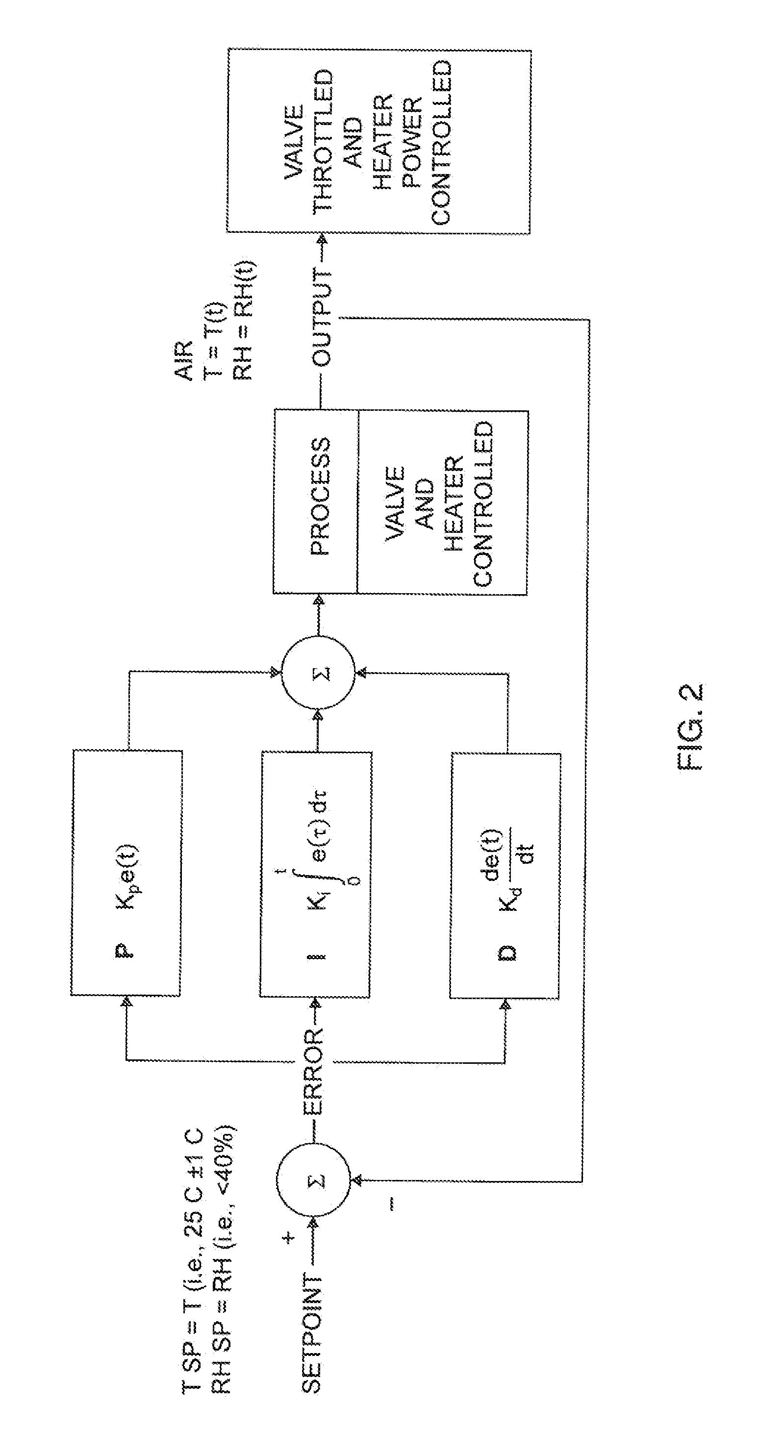
[0011]A processor or controller has inputs coupled to the air temperature sensors and to the air pressure sensors. The controller is configured to supply the air control valve signal and the heater signal according to certain humidity and temperature set points required for the payload in the equipment bay enclosure. Accordingly, the inventive control system enables reliable temperature and humidity control in unpressurized equipment bays at altitudes of up to 60,000 feet or higher.

Problems solved by technology

The performance of optical system components is affected greatly by thermal expansion and contraction.
Additionally, opto-mechanical and electronic components that are integrated within precision optical systems are also sensitive to temperature and moisture.
Disadvantages of either system are that the ACM and the VCM machines each weigh approximately 100 pounds and consume a large amount of electrical power and critical volume aboard an aircraft.
Also, the cost of either system typically exceeds $100,000, with a mean-time-between-failures (MTBF) of only about 4,000 flight-hours.
As far as is known, however, cyclone separators have not been used in systems for controlling the thermal environment of sensitive airborne payloads.

Method used


Image

  • Environmental control system for precision airborne payloads
  • Environmental control system for precision airborne payloads
  • Environmental control system for precision airborne payloads

Examples


example

[0033]The following is an example of the operation of the inventive system 10 to achieve environmental control between 10 deg. C. and 40 deg. C. inside the bay enclosure 20 over the course of an aircraft mission. The table in FIG. 3 illustrates the system operation over those portions of the mission between ground operation, take-off, ascent to an altitude of 20,000 feet (20 kft) or higher, and descent from 20 kft.

[0034]During ground operation, the ram air control valve 30 is opened to allow a ground cooling cart to provide conditioned air into the equipment bay 20. With the ground cooling cart connected, the environment inside the bay enclosure 20 is conditioned to a desired temperature and relative humidity. The air heater assembly 50 is preferably turned ON if the bay temperature sensors 56 indicate a temperature of less than 10 deg. C., and the heater assembly is turned OFF when the air temperature is above 10 deg. C. (or 15 deg. C. if a 5 deg. C. hysteresis is desired).

[0035]Al...


PUM


Abstract

Outside air enters a ram air scoop on an aircraft frame, and is ducted to a ram air control valve. The air control valve outputs a desired air mass flow to a cyclone air-water separator which removes moisture and produces a dry air flow. A heater assembly heats the dry air to a desired temperature and directs the heated air into an equipment bay enclosure on the aircraft. The relative humidity of the heated air is sensed by an air moisture sensor which produces a corresponding signal. Other sensors disposed near a payload in the bay enclosure produce corresponding air temperature and air pressure signals. All the sensor signals are input to a processor or controller configured to activate the air control valve and the heater assembly according to set points for temperature and humidity that are specified for the payload in the bay enclosure.

Description

BACKGROUND OF THE INVENTION[0001]1. Field of the Invention[0002]The present invention relates to environmental control systems, and particularly to systems that provide controlled temperature and humidity environments for airborne payloads.[0003]2. Discussion of the Known Art[0004]Airborne reconnaissance, surveillance, and electronics payloads are typically mounted in an unpressurized equipment bay on an aircraft, and are expected to operate reliably at altitudes from sea level to 60,000 feet or higher above mean sea level. Such payloads often include precision optics, focal plane arrays, and electronics. The electronic equipment may include recorders, data links, sensor control units, control electronics units, and countermeasures systems.[0005]The performance of optical system components is affected greatly by thermal expansion and contraction. Additionally, opto-mechanical and electronic components that are integrated within precision optical systems are also sensitive to tempera...

Claims


Application Information

Patent Timeline
Patent Type & Authority Applications(United States)
IPC IPC(8): G05B15/00G05D7/00B60H3/00B64D13/00B64D13/04
CPCB64D13/06B64D2013/0614Y02T50/56B64D2013/0662G05B11/42B64D2013/0618Y02T50/50
Inventor ENGELHARDT, MICHEL
Owner BAE SYST INFORMATION & ELECTRONICS SYST INTERGRATION INC
Learn More