Light Emitting Device and Manufacturing Method Thereof
a technology of light emitting devices and manufacturing methods, applied in the direction of solid-state devices, semiconductor devices, thermoelectric devices, etc., can solve the problems of high film resistance of transparent electrodes and restricted opening ratios
- Summary
- Abstract
- Description
- Claims
- Application Information
AI Technical Summary
Benefits of technology
Problems solved by technology
Method used
Image
Examples
embodiment mode 2
[0117]A method of combining a white color luminescent element and a color filter (hereinafter, referred to as color filter method) will be explained in reference to FIG. 5A as follows.
[0118]The color filter method is a system of forming a light emitting element having an layer containing an organic compound layer displaying white color luminescence and passing the provided white color luminescence through a color filter to thereby achieve luminescence of red, green, and blue.
[0119]Although there are various methods of achieving white color luminescence, a case of using a luminescent layer comprising a high molecular material formable by coating will be explained here. In this case, doping of a color pigment to the high molecular material for constituting a luminescent layer can be carried out by preparing a solution and can extremely easily be achieved in comparison with a vapor deposition method for carrying out common vapor deposition for doping a plurality of color pigments.
[0120...
embodiment mode 3
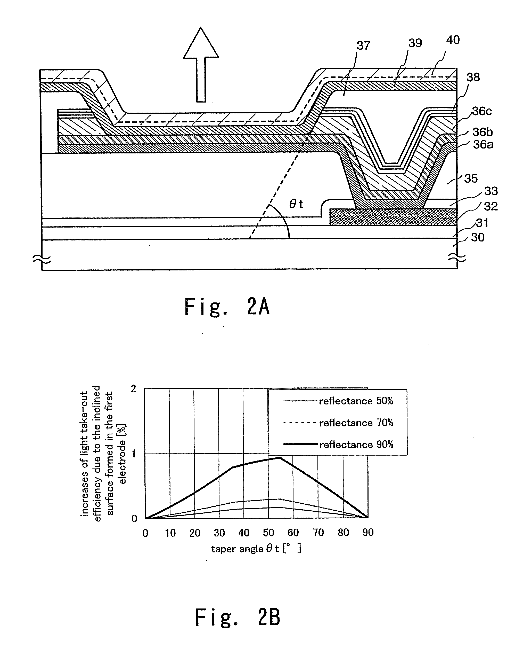
[0134]Other example of the structure is to be described with reference to FIG. 4. Since the embodiment in FIG. 4 is identical with the embodiment of FIG. 2 except for a certain portion, identical portions carry same reference numerals.
[0135]In FIG. 4, after laminating a titanium nitride film 40 on a titanium film 36a to a thickness slightly larger than that of FIG. 2, a portion of the titanium nitride film 40 is also formed as an inclined surface by etching. Since other structures are identical with those in FIG. 2, detailed descriptions of them will be omitted.
[0136]Further, this embodiment mode can be optionally combined with Embodiment Mode 1 or Embodiment Mode 2.
[0137]The present invention comprising the foregoing constitutions is to be described more specifically with reference to examples described below.
embodiment 1
[0138]In this embodiment, a brief description is given with reference to FIGS. 2A to 3C on an example of procedure of forming a light emitting element in accordance with the present invention.
[0139]First, a base insulating film 31 is formed on a substrate 30 which has an insulating surface.
[0140]The base insulating film 31 is a laminate and the first layer is a silicon oxynitride film formed to have a thickness of 10 to 200 nm (preferably 50 to 100 nm) by plasma CVD using as reaction gas SiH4, NH3, and N2O. Here, a silicon oxynitride film (composition ratio: Si=32%, O=27%, N=24%, H=17%) with a thickness of 50 nm is formed. The second layer of the base insulating film is a silicon oxynitride film formed to have a thickness of 50 to 200 nm (preferably 100 to 150 nm) by plasma CVD using as reaction gas SiH4 and N2O. Here, a silicon oxynitride film (composition ratio: Si=32%, O=59%, N=7%, H=2%) with a thickness of 100 nm is formed. Although the base insulating film 108 in this embodimen...
PUM
 Abstract
Description
Claims
Application Information
 - R&D
- Intellectual Property
- Life Sciences
- Materials
- Tech Scout
- Unparalleled Data Quality
- Higher Quality Content
- 60% Fewer Hallucinations
Browse by: Latest US Patents, China's latest patents, Technical Efficacy Thesaurus, Application Domain, Technology Topic, Popular Technical Reports.
© 2025 PatSnap. All rights reserved.Legal|Privacy policy|Modern Slavery Act Transparency Statement|Sitemap|About US| Contact US: help@patsnap.com


