Turning-stabilized estimation of the attitude angles of an aircraft

Active Publication Date: 2011-08-04
EUROCOPTER
View PDF5 Cites 44 Cited by
  • Summary
  • Abstract
  • Description
  • Claims
  • Application Information

AI Technical Summary

Benefits of technology

[0019]make it easier to incorporate MEMS gyros in an AHRS;
[0021]ensure that the attitude, heading, and vertical filters are separable into sub-filters, thereby ensuring simplicity, and thus making it possible to prove the system is stable, e.g. for certification.
[0030]Each of the coefficients of said linear combination is a continuous function of time and depends on said estimated rate of turn; such that the estimated attitude angles are stable, including while the aircraft is turning.
[0060]It will also be seen that the invention seeks to resolve the processing into sub-filters, that are proved to be independent, and that are sufficiently simple to enable stability to be proved mathematically. This makes it possible to obtain an attitude estimate in accordance with the invention that is functionally reliable, e.g. up to a safety-critical level.
[0062]It will also be understood that the invention preserves the simplicity of the attitude filter, which filter is not entangled with the heading filter or the vertical speed filter, thus making it possible to obtain certification at a safety-critical level.

Problems solved by technology

The drawback of that approach is that any variations in gyro measurement bias that take place after the bias has been frozen are no longer compensated.
In contrast, when the gyros of an attitude unit are of lower performance, that can lead to said attitude unit producing significant errors in its estimates of attitudes and of heading.
Furthermore, it is presently not possible for an attitude unit to include gyros presenting estimated error or bias that is of the order of several tens of degrees per hour.
A fortiori, this is completely impossible if it is desired to obtain safety-critical certification.
Nevertheless, low-cost vibrating gyros exist in MEMS form.
With present techniques, such MEMS gyros present biases that are too great for them to be included in an attitude unit.

Method used


Image

  • Turning-stabilized estimation of the attitude angles of an aircraft
  • Turning-stabilized estimation of the attitude angles of an aircraft
  • Turning-stabilized estimation of the attitude angles of an aircraft

Examples


Embodiment Construction

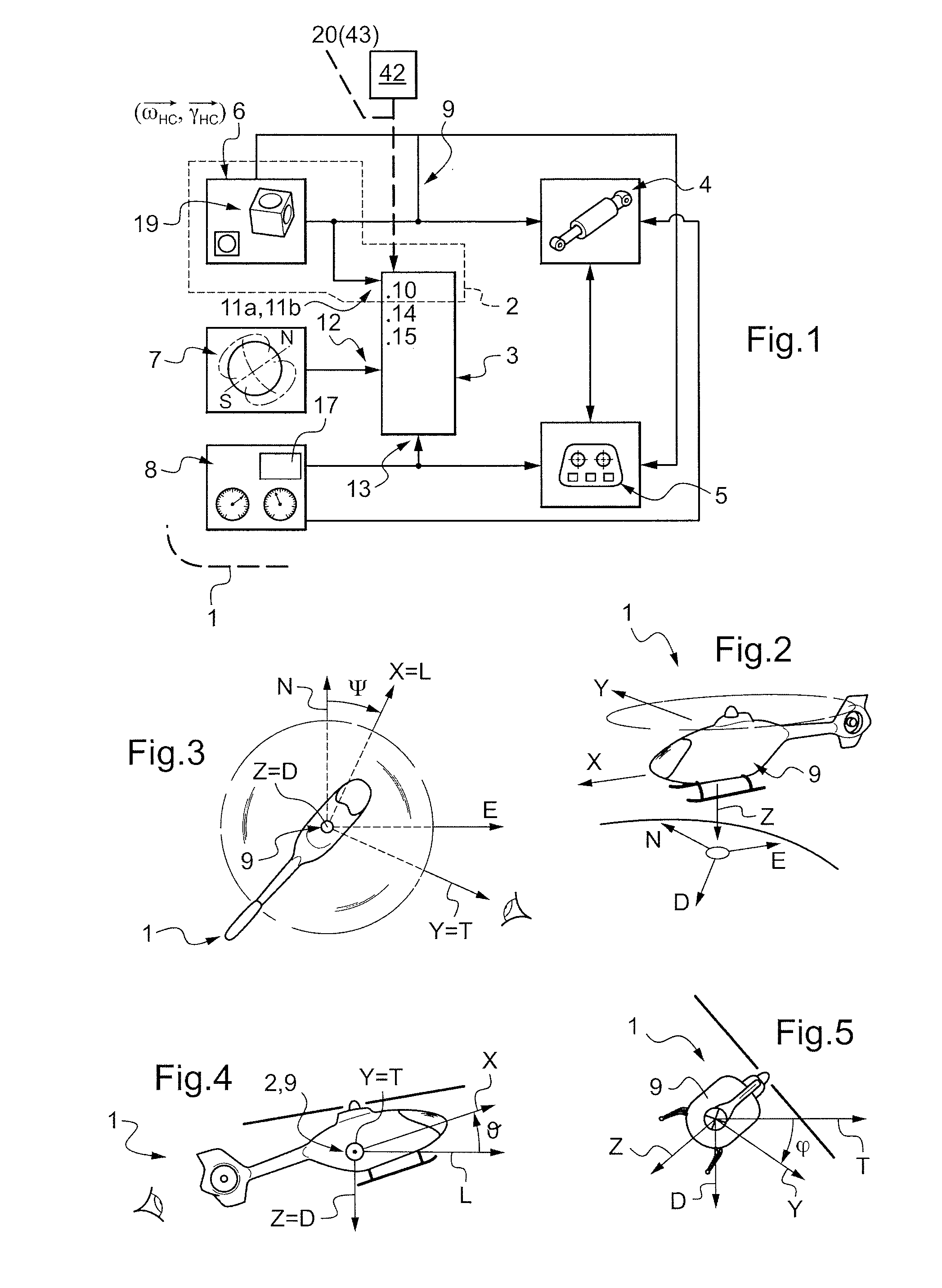
[0072]In FIGS. 1 to 6, overall numerical reference designates an aircraft. In FIGS. 2 to 5, the aircraft 1 is a helicopter, but this is not limiting.

[0073]In FIG. 1, there can be seen various pieces of piloting assistance equipment on board an aircraft 1 in accordance with the invention. In particular, the aircraft 1 includes an attitude unit 2. By way of example, reference 2 designates an “AHRS” system and / or emergency instruments of the aircraft 1, such as an integrated electronic standby instrument (IESI). In general, in an aircraft 1, there are found to be both an AHRS type system and emergency instruments.

[0074]The unit 2 includes in particular a computed virtual platform 3.

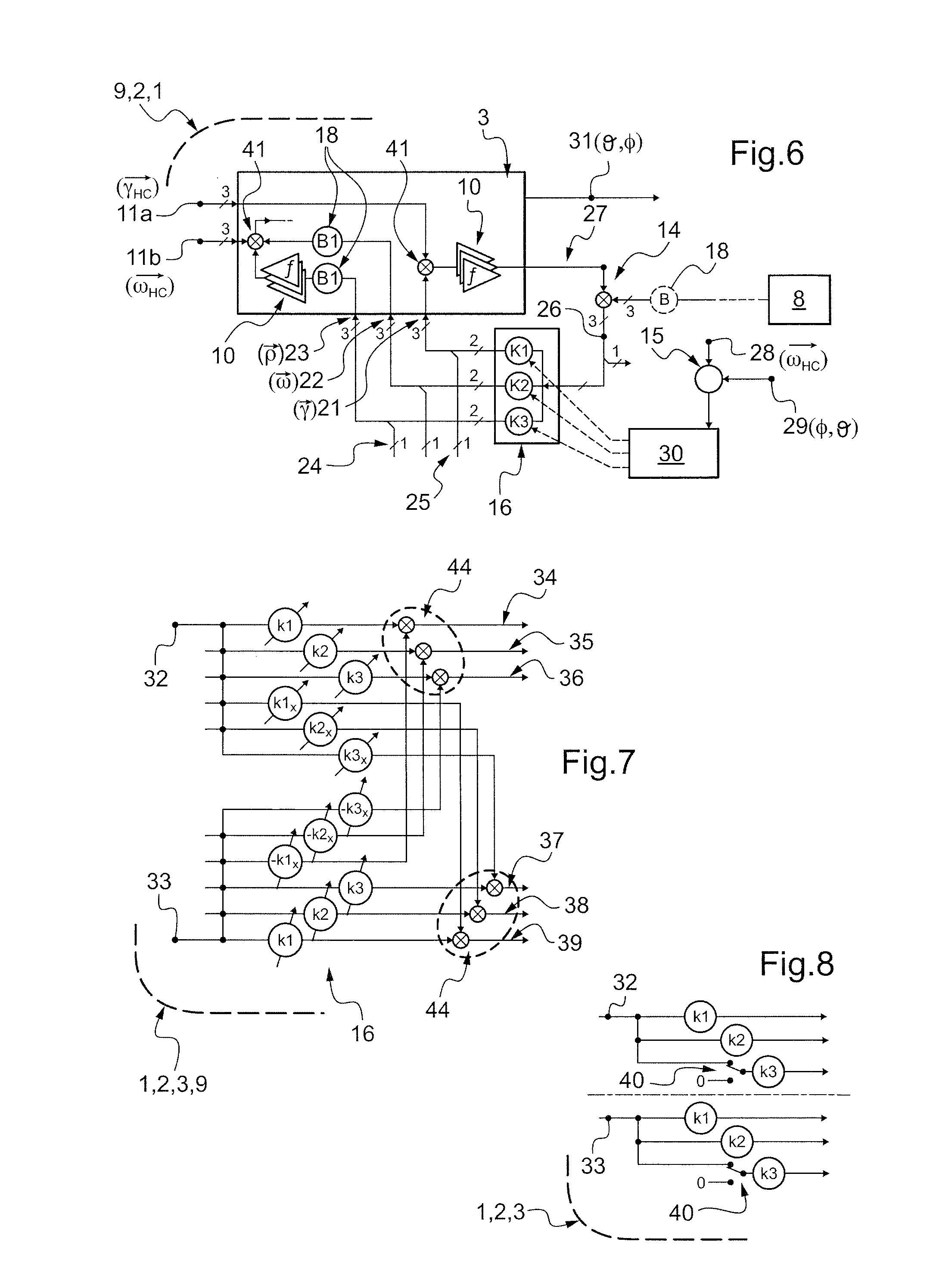
[0075]The platform 3 performs computations to maintain an estimate of the directions of the navigation axes, this estimate suffering from three angle errors: two angles of inclination relative to the true level plane, and the azimuth angle defined relative to the direction of true magnetic north.

[0076]FIG. 1...


PUM


Abstract

The present invention relates to estimating the attitude angles of an aircraft (1). The estimated attitude angles are generated by a device (9) that performs algorithmic integration on inertial measurements indicative of an angular velocity and of a linear acceleration. Horizontal components (34-39) of desired corrections are obtained by a linear combination of two horizontal components (32-33), with cross coefficients between said horizontal axes being continuous variable over time and dependent on the estimated rate of turn. As a result, the estimated attitude angles are stable, and the biases of the gyros continue to be estimated, including during stages during which the aircraft (1) is turning.

Description

CROSS REFERENCE TO RELATED APPLICATIONS[0001]This application claims the benefit of FR 10 00380 filed on Jan. 29, 2010, the disclosure of which is incorporated in its entirety by reference herein.FIELD OF THE INVENTION[0002]The general field of the present invention is that of piloting assistance for aircraft.[0003]In particular, the present invention relates to measuring the attitudes of such an aircraft. Typically, it applies to attitude units. These measurements are used mainly for displays for use by the pilot of the aircraft (via a piloting flight display (PFD) or a flight display system (FDS)), and also by an autopilot system, or automatic flight control system (AFCS).[0004]Among the attitude units concerned, the present invention is applicable for example to so-called attitude and heading reference systems (AHRS) or indeed to emergency instruments, e.g. known as integrated electronic standby instruments (IESIs).BACKGROUND OF THE INVENTION[0005]An example of an attitude and he...

Claims


Application Information

Patent Timeline
IPC IPC(8): G05D1/00
CPCG01C21/16G01C21/185G01C21/188
Inventor PETILLON, JEAN PAUL
Owner EUROCOPTER
Why Eureka
Try Eureka