Servo controlled docking force device for use in ophthalmic applications

a technology of docking force and servo control, which is applied in the field of servo controlled docking force device for use in ophthalmic applications, can solve the problems of time-consuming process and inability of existing ultrashort pulse ophthalmic lasers to automatically regulate the force applied to the eye, and achieve the effect of quick registration and immobilization of the ey

Inactive Publication Date: 2011-08-04
LENSAR LLC
View PDF42 Cites 75 Cited by
  • Summary
  • Abstract
  • Description
  • Claims
  • Application Information

AI Technical Summary

Benefits of technology

[0008]One or more aspects of the present invention allow for a quick registration and immobilization of an eye.

Problems solved by technology

However, the existing ultrashort pulse ophthalmic lasers do not have any automatic means to regulate the force applied to the eye.
The above described docking process using the PID is a manual operation and so it can be a time consuming process.

Method used


Image

  • Servo controlled docking force device for use in ophthalmic applications
  • Servo controlled docking force device for use in ophthalmic applications

Examples


Embodiment Construction

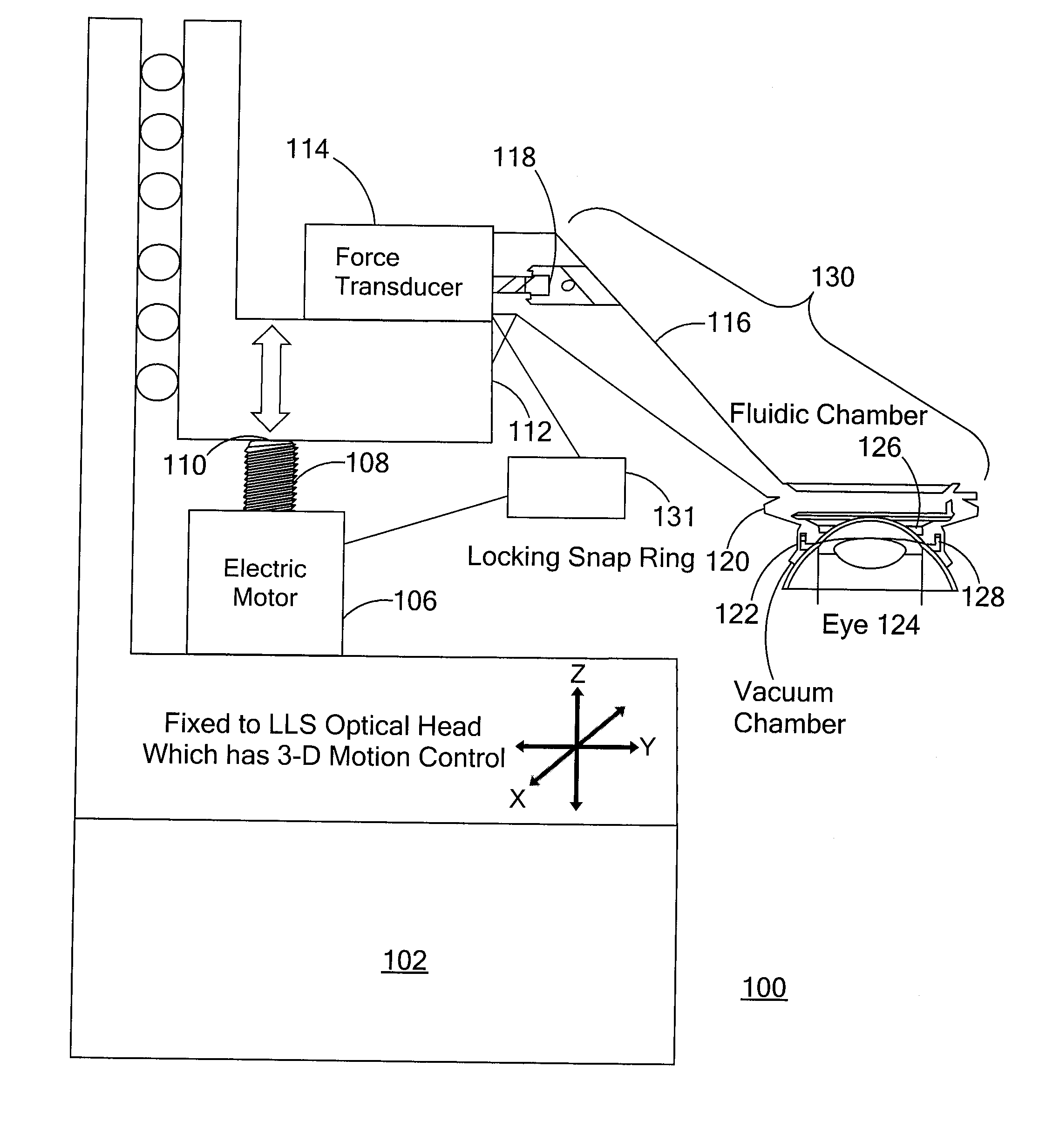
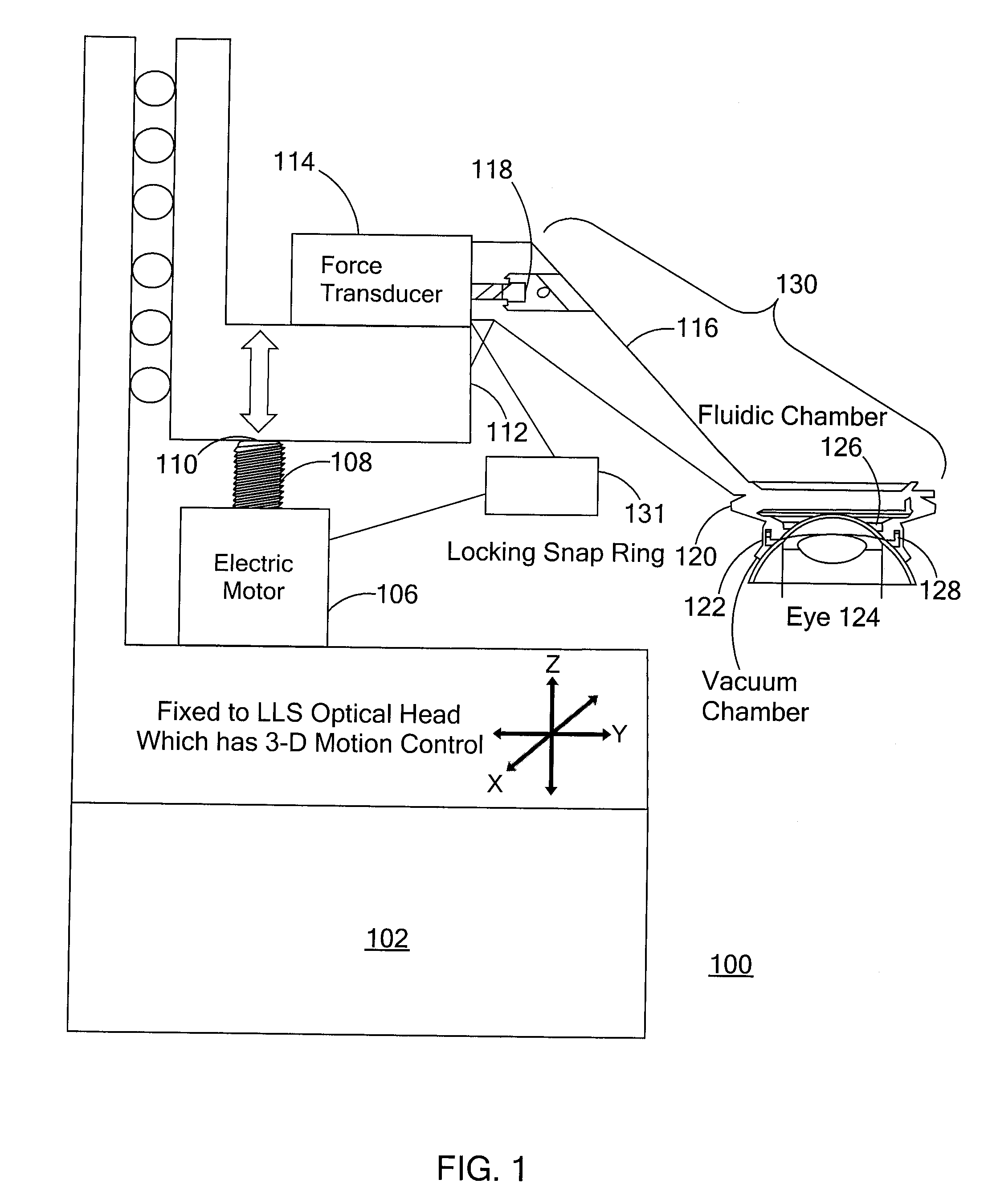
[0011]As schematically shown in FIG. 1, a laser treatment system 100 includes a laser system wherein only the optical head 102 is shown for convenience. The optical head moves in three dimensions in a well known manner via a three-dimensional motion control. Examples of possible laser systems that can be used are the laser systems described in U.S. patents applications Ser. Nos. 11 / 337,127; 12 / 217,285; 12 / 217,295; 12 / 509,412; 12 / 509,021; 12 / 509,211 and 12 / 509,454, the entire contents of each of which are incorporated herein by reference.

[0012]As shown in FIG. 1, an electric motor 106 is attached to the optical head 102. The electric motor 106 drives a translatable item, such as a screw 108, in the +z or −z directions. An end 110 of the screw 108 engages a translatable platform 112 that is able to move in the +z or −z directions. Thus, when the screw 108 engages platform 112 when moving in the +z direction, the platform 112 will also move in the +z direction. Similarly, when the scre...


PUM


Abstract

A laser treatment system that includes means for applying a laser beam to an eye of a patient and means for registering and immobilizing the eye.

Description

[0001]This application claims the benefit of priority under 35 U.S.C. § 119(e)(1) of: 1) U.S. Provisional Application Ser. No. 61 / 299,536 titled Servo Controlled Docking Force Device for Use in Ophthalmic Applications, filed Jan. 29, 2010 and 2) U.S. Provisional Application Ser. No. 61 / 300,167 titled Servo Controlled Docking Force Device for Use in Ophthalmic Applications, filed Feb. 1, 2010, the entire contents of each of which is incorporated herein by reference.FIELD OF THE INVENTION[0002]The present invention relates to a device to register and immobilize a patient's eye during a medical procedure, such as an ophthalmic procedure, and more particularly, the delivery of a treatment laser to the cornea of the eye.BACKGROUND[0003]It is known to use a patient interface device (PID) with ophthalmic ultrashort pulse lasers used for cutting corneal or crystalline lens tissue of a patient's eye. The PID has two parts: a suction ring which is applied manually to the patient's eye and an ...

Claims


Application Information

Patent Timeline
IPC IPC(8): A61F9/009
CPCA61F9/00825A61F2009/00872A61F2009/0087A61F9/009
Inventor FREY, RUDOLPH W.BOTT, STEVEN E.
Owner LENSAR LLC
Why Eureka
Try Eureka