
Telephone call handling system

a call handling and telephone technology, applied in the field of telephone call handling system, can solve the problems of caller id. being flawed, every caller having to be inconvenienced in providing call-announce information, and caller id. not providing the true identity of the caller, etc., to improve the utilization rate of caller id, improve the utilization rate, and save time/productivity

Inactive Publication Date: 2011-08-04
WILLIAMS CHRISTOPHER GUY
View PDF4 Cites 18 Cited by
  • Summary
  • Abstract
  • Description
  • Claims
  • Application Information

AI Technical Summary

Benefits of technology

[0005]In this ever-accelerated world, unknown / unwanted calls answered and unknown yet wanted calls not answered, all due to the shortcomings of caller I.D., costs time / productivity. U.S. Pat. No. 7,062,034 to Williams discloses an invention that cures said caller I.D. shortcomings. Williams discloses a number of embodiments where call-announce information is attained from the caller and delivered to the user. Williams describes attaining call-announce information whereby the caller is asked to speak their name. From the spoken name information and in the caller's voice, the user can readily identify the individual who's calling.
[0007]The present disclosure provides for a telephone call handling system, certain embodiments of which achieve improved utilization of caller I.D. information (improved beyond a user receiving caller I.D. information and therefrom simply deciding whether to answer the phone or not). The improved utilization of the caller I.D. information produces improved fluency and continuity to telephone call communication, saves caller and user time and enables selective entertainment of caller and / or user.
[0009]A second example description of operation of another embodiment of the present invention provides another example of said greater fluidity and continuity while saving the user's time and providing convenience to the user. The incoming call includes caller I.D. information. From the information, the user is essentially able to determine the identity of the caller. However, the user is presently occupied with other matters. Consequently, the user starts a message-then-hold circuitry. In response, the circuitry sends the message to the caller, “I'll be right with you”. The circuitry then retains connection with the caller, circuitry and caller waiting for the user to answer the call. When the user is no longer preoccupied, the user may then answer the call. Message-then-hold frees the user from the messy / uncomfortable and time consuming action of having to answering the call and notifying the caller he is to be placed on hold.

Problems solved by technology

Caller I.D. is flawed in that the telephone number and name provided belong to the subscriber of the calling telephone.
Conversely, often times a caller simply happens to be calling from someone else's phone, a pay phone, an out-of-area phone or a family shared phone and, thus, caller I.D. will not provide the user with the true identity of the caller.
In this ever-accelerated world, unknown / unwanted calls answered and unknown yet wanted calls not answered, all due to the shortcomings of caller I.D., costs time / productivity.
However, if the user desires to know the identity of every caller, every caller must be inconvenienced to provide the call-announce information.

Method used


Image

  • Telephone call handling system
  • Telephone call handling system
  • Telephone call handling system

Examples


first embodiment

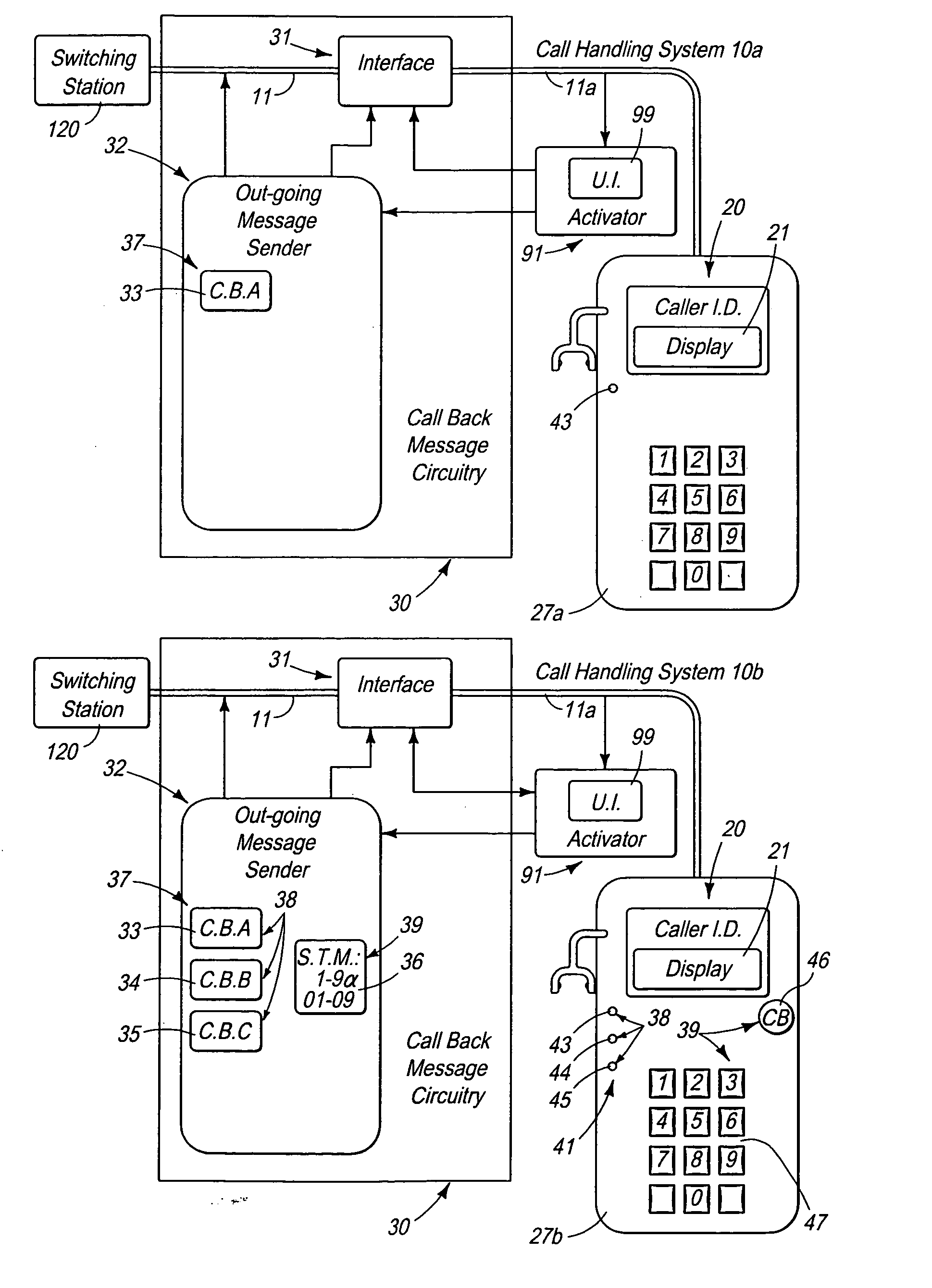
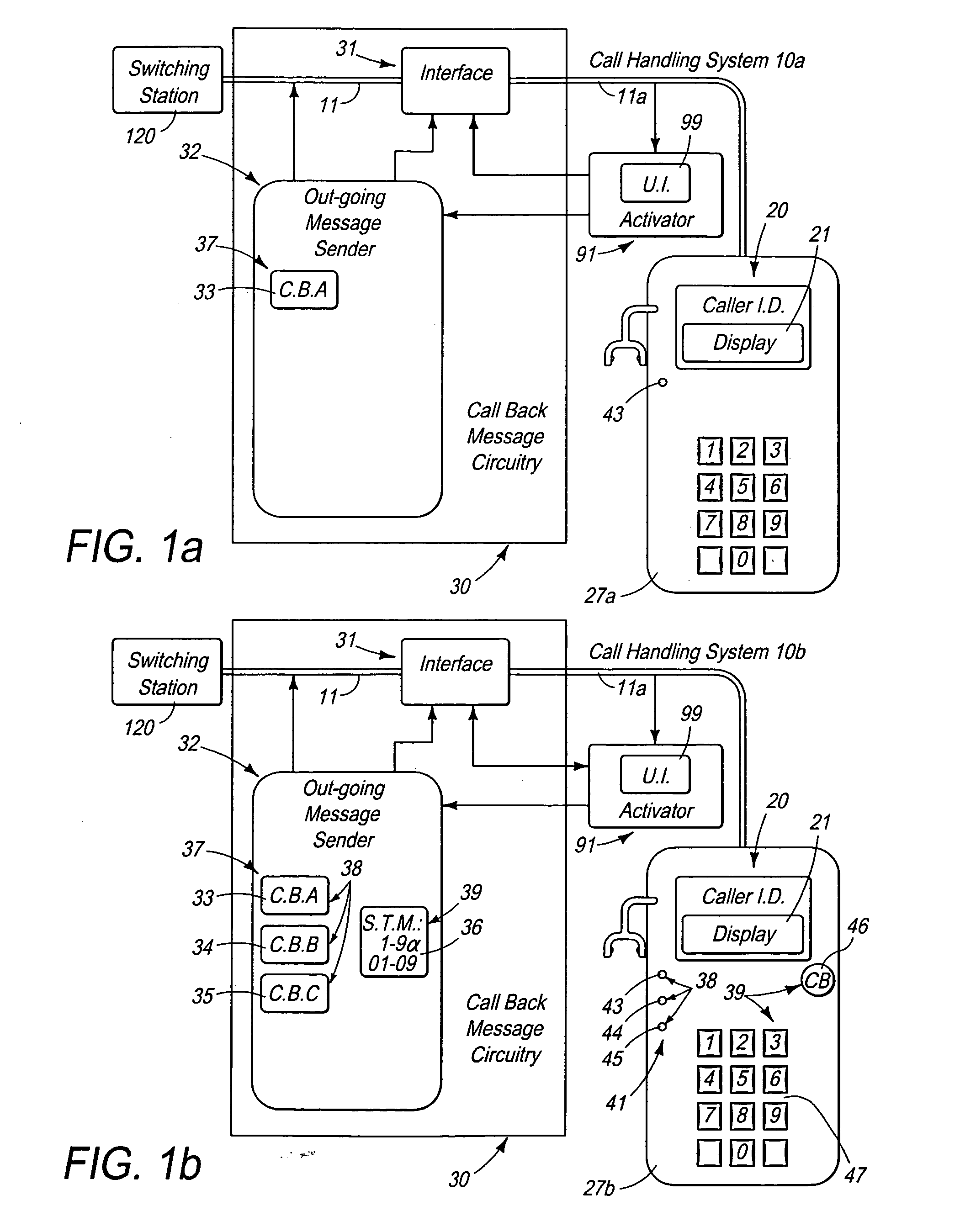
[0041]A first example of this first embodiment is illustrated as system 10a in FIG. 1a. For this example, out-going message sender 32 of callback circuitry 30 is configured to deliver to a caller a callback message A 33 shown as C.B. A 33. Callback message A 33 states, “Please call back in one hour”. (The message, “Please call back in one hour” constitutes a specific time callback message 37, shown in FIGS. 1a and 1b. Conversely, callback messages can state, for example, “I'll call you back in one hour”.) Message sender 32 is further configured to send a signal to interface 31 at the conclusion to the sending of the message.

[0042]For this example, UI 99 of activator 91 is configured to receive instruction from a user via a control button 43, button 43 electrically connected to (or connectable to) line 11a and located at telephone 27a. When pressed, button 43 is configured to send a control signal via line 11a to UI 99. UI 99 responds by sending a signal to interface 31 and, after a ...

second embodiment

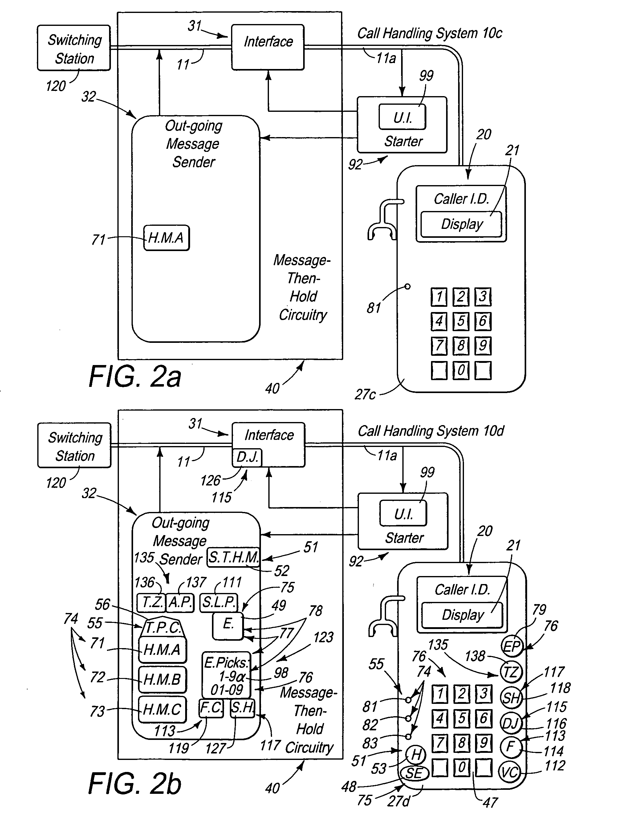
[0056]A first example of this second embodiment is illustrated as system 10c in FIG. 2a. For this example, out-going message sender 32 of message-then-hold circuitry 40 is configured to store and to deliver to a caller a hold message A 71 shown as H.M. A 71. Hold message A 71 states, “I'll be right with you”. Interface 31 is configured to maintain the off-hook condition until detecting the call being answered by the user.

[0057]Further for this example, UI 99 of starter 92 is configured to receive instruction from a user via a control button 81, button 81 electrically connected to (or connectable to) line 11a and located at telephone 27c. When pressed, button 81 sends a control signal to UI 99. UI 99 responds by sending a signal to interface 31 and, after a two-second delay, sending a signal to sender 32. Interface 31 responds by going off-hook. Sender32 responds by sending hold message A 71 to the caller. (Button 81 can be part of starter 92.)

[0058]An example of operation of this fi...

third embodiment

[0085]A first example of this third embodiment is illustrated as system 10e in FIG. 3a. For this example, out-going message sender 32 of concert circuitry 50 is configured to provide stored entertainment 49 of user-selected deployed entertainment 75 to a caller. Sender 32 is further configured to send entertainment 49 to information signal provider 85. Information signal provider 85 is configured to receive entertainment 49 from message sender 32 and to send entertainment 49 to deliverer 100 via line 11a. (Stored entertainment 49 and deployed entertainment 75 described prior. Entertainment 49 can comprise music 77 and / or interesting sound 78 shown in FIGS. 2b, 3a, 3b and 8, described prior.) Stored entertainment 49 can comprise a song-last-played 111 (shown as S.L.P. 111 in FIGS. 2b, 3a, 3b and 8.) As an example, if handling system 10 is being employed as a music player (or other) and stored entertainment 49 (or pick storage 98 or other) is being played, message sender 32 is configu...


PUM


Abstract

A telephone call handling system includes a text selector to enable a user to select a text message prior to an incoming call. The text message can be stored in a text storage and sent by a text sender from the text storage for receipt at a caller's telephone during and / or after the incoming call. A delivery trigger can trigger the text sender to send the text message. The delivery trigger can be linked to delivery of an audio message, an audio content, an image or a video. The delivery trigger can be linked to call detection, call answer or call hang up. The user can be enabled to trigger the sending of the text message. The system can further include caller I.D. information. The user can employ the caller I.D. information in making a trigger decision.

Description

CROSS REFERENCE TO RELATED APPLICATIONS[0001]This is a continuation in part of co-pending U.S. patent application Ser. No. 12 / 658,475 filed Feb. 4, 2010, which is hereby incorporated by reference herein in it's entirety.BACKGROUND[0002]A call screening service commonly known as “Caller I.D.” is widely utilized by present-day telephone users. Caller I.D. is a service provided to users by the telephone service providers via telephones typically fitted with a display. For calls from landline phones, the caller I.D. information typically displayed includes the telephone number of the landline phone a caller is calling from and the subscriber name documented to that number. For calls from cell phones, the information typically displayed includes the telephone number of the cell phone a caller is calling from and whatever name the cell phone owner happens to program into his phone (or not).[0003]Present-day, telephone users having caller I.D. typically first respond to an incoming telepho...

Claims


Application Information

Patent Timeline
Patent Type & Authority Applications(United States)
IPC IPC(8): H04W4/12
CPCH04W4/12H04M1/72436H04M3/42382H04M1/7243H04W4/16H04W4/14
Inventor WILLIAMS, CHRISTOPHER GUY
Owner WILLIAMS CHRISTOPHER GUY
Learn More