
Method and apparatus for measuring properties of a compound

a technology of compound and measuring device, applied in the direction of instruments, diaphragms/collimeters, diaphragms for radiation diagnostics, etc., can solve the problems of long imaging time, mechanical scanning, and reduced imaging tim

Active Publication Date: 2011-08-04
UNIV OF ILLIONIS URBANA CHAMPAIGN
View PDF3 Cites 19 Cited by
  • Summary
  • Abstract
  • Description
  • Claims
  • Application Information

AI Technical Summary

Problems solved by technology

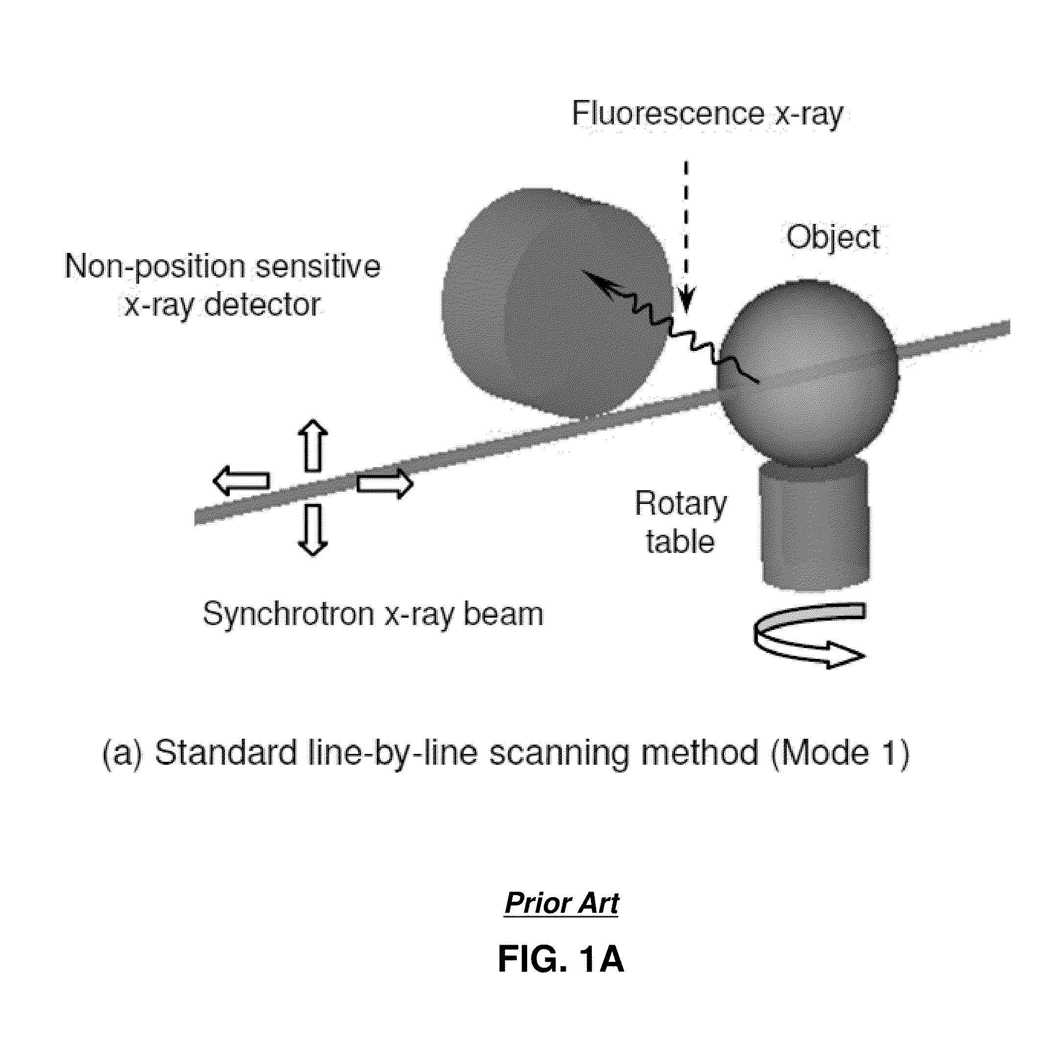
Despite the excellent imaging performances demonstrated in these studies, the need for mechanical scanning leads to long imaging times. In recent years, many efforts have been dedicated to improve the speed of XFCT studies [6], [7].
In comparison to the conventional line-by-line scanning scheme, the ET-based imaging system allows a great reduction in imaging time, which has been one of the major hurdles for current XFCT studies.
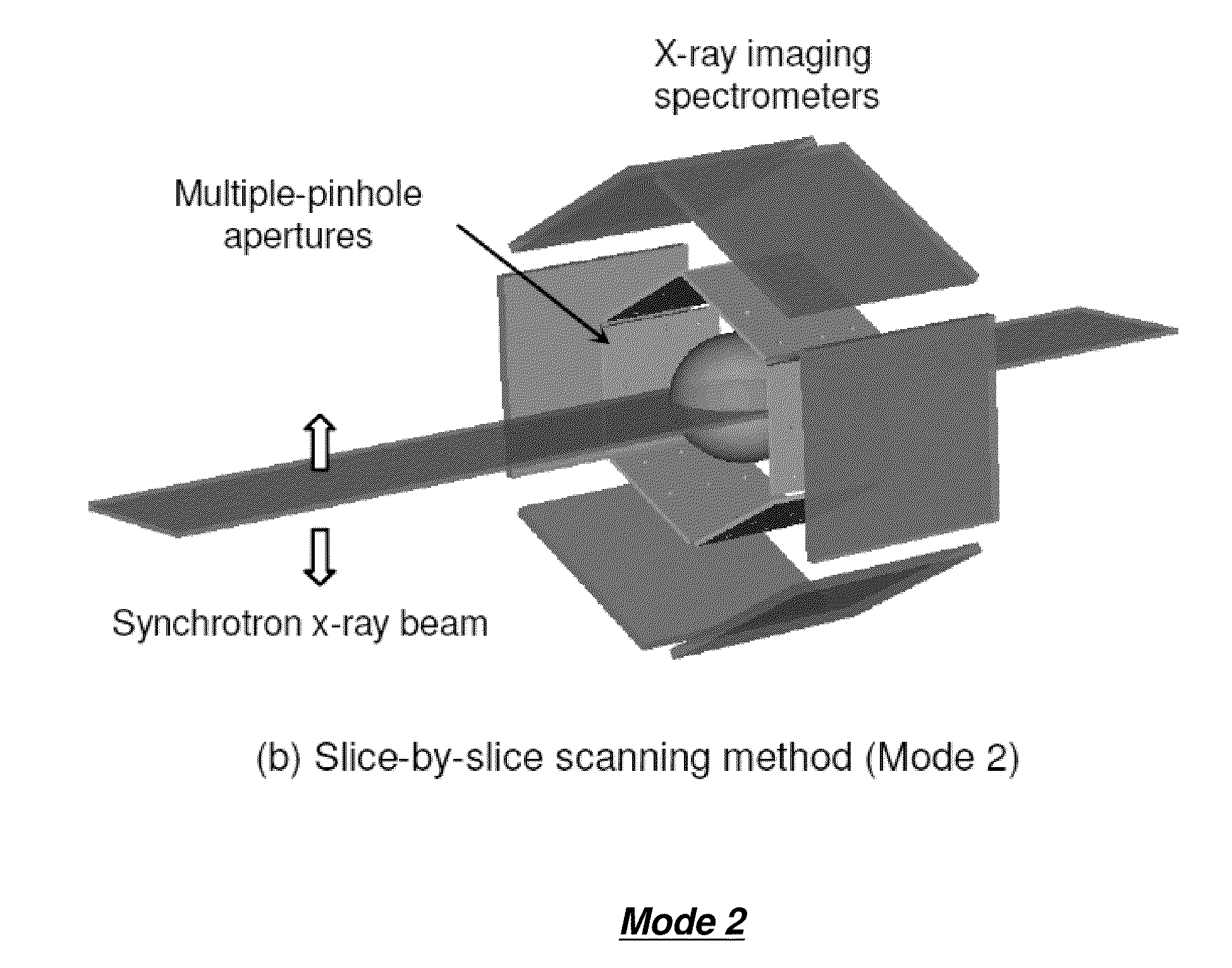
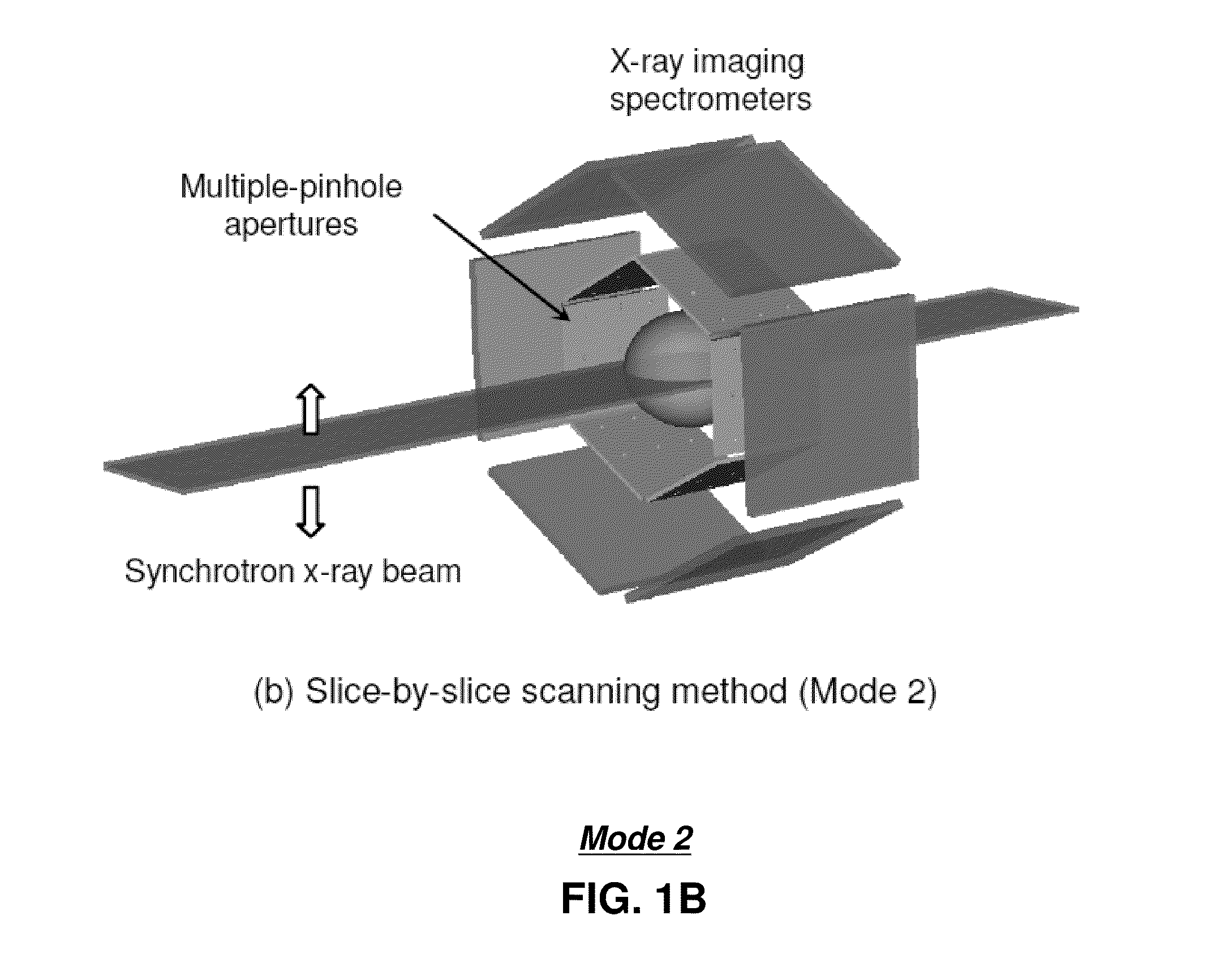
Firstly, with Mode 2 and 3 geometries (shown in FIG. 1), the much-simplified scanning motions would potentially lead to a much-reduced imaging time.
Secondly, with the line-by-line scanning, the angular sampling achieved is limited by (a) the mechanical scanning procedures that can be practically implemented and (b) the constraints on imaging time and dose delivery during the measurement.
Firstly, high-resolution SPECT detection systems typically require the use of collimation apertures that have very small open-fractions (10−3-10−2).
Therefore, the key uncertainty is whether the use of ET-based can provide an improved signal-to-noise ratio with comparable imaging times. Secondly, Mode 2 and 3 tend to deliver a greater amount of radiation dose per unit imaging time.
Although radiation doses may not be a serious issue for nonbiological samples, it does pose limitations for potential in vivo studies [9][10].
Thirdly, the spatial resolution provided by Mode 2 and 3 geometries is limited by the size of the pinholes.
Given the constraints on aperture fabrication and the considerations on detection efficiency, the use of pinholes of less than 25 μm diameter is less practical.
Therefore, the spatial resolution offered by the ET-based detection system is typically limited to several tens of microns to a few hundred microns.
In comparison, the line-by-line scanning scheme allows for a spatial resolution at submicron level, although this would require a long imaging time.
Unfortunately, the beam was mistakenly aimed too high and missed the section containing most of the solutions.

Method used


Image

  • Method and apparatus for measuring properties of a compound
  • Method and apparatus for measuring properties of a compound
  • Method and apparatus for measuring properties of a compound

Examples


Embodiment Construction

[0017]One embodiment of the present disclosure entails an apparatus having a collimator and a fluorescence detector. The collimator can be positioned next to a compound. The collimator can have at least one aperture. The aperture can be made of a thin sheet of heavy metal, such as gold and tungsten, with openings machined through the metal sheet. The compound emits fluorescence X-rays when impacted by an X-ray beam generated by an X-ray source. The collimator in turn can absorb at least a first portion of the fluorescence X-rays emitted by the compound and allow a second portion of the fluorescence X-rays to pass through the aperture to be detected by the fluorescence detector placed in proximity to the aperture. A three-dimensional (3-D) rendering of an elemental distribution of the compound can be determined from the fluorescence X-rays detected and the directional information.

[0018]One embodiment of the present disclosure entails a method for receiving fluorescence X-rays respons...


PUM


Abstract

A system that incorporates teachings of the present disclosure may include, for example, an apparatus having a collimator having at least one aperture and a fluorescence detector. The collimator can be positioned next to a compound. The compound can emit fluorescence X-rays when impacted by an X-ray beam generated by an X-ray source. The collimator can absorb at least a first portion of the fluorescence X-rays emitted by the compound and release at least a second portion of the fluorescence X-rays at the at least one aperture. The second portion of the fluorescence X-rays released by the at least one aperture have known directional information based on a position of the collimator. The fluorescence detector can detect the second portion of the fluorescence X-rays released by the at least one aperture. A three-dimensional (3-D) rendering of an elemental distribution of the compound can be determined from the fluorescence X-rays detected and the directional information. Additional embodiments are disclosed.

Description

PRIOR APPLICATION[0001]The present application claims the benefit of priority to U.S. Provisional Application No. 61 / 293,118 filed on Jan. 7, 2010, which is hereby incorporated herein by reference.STATEMENT AS TO FEDERALLY SPONSORED RESEARCH[0002]This invention was made with government support under DE-AC02-06CH11357 awarded by Argonne National Laboratory and the Department of Energy. The government has certain rights in this invention.FIELD OF THE DISCLOSURE[0003]The present disclosure relates generally to a method and apparatus for measuring properties of a compound.BACKGROUND[0004]Fluorescence X-ray techniques are widely used for elemental analysis. It offers an excellent sensitivity to trace elements down to picogram level. With the use of synchrotron X-ray sources, 3-D mapping of trace elements inside volumetric samples can be obtained with the so-called fluorescence X-ray computed tomography (XFCT) techniques [1]-[10]. In most of XFCT studies, a pencil-beam of synchrotron X-ra...

Claims


Application Information

Patent Timeline
IPC IPC(8): G01N23/223
CPCG01N23/223G01N2223/076A61B6/032A61B6/06G21K1/02
Inventor MENG, LING JIAN
Owner UNIV OF ILLIONIS URBANA CHAMPAIGN
Learn More