
Systems, Apparatus and Methods for Coating the Interior of a Container Using a Photolysis and/or Thermal Chemical Vapor Deposition Process

a technology of glass container, which is applied in the field of systems, apparatuses and methods for photolysis and/or thermal chemical vapor deposition (cvd), can solve the problems of affecting the shelf life affecting the quality of the packaged product, so as to facilitate the deposition and polymerization of the reactive moiety

Inactive Publication Date: 2011-08-04
BECTON DICKINSON & CO
View PDF35 Cites 52 Cited by
  • Summary
  • Abstract
  • Description
  • Claims
  • Application Information

AI Technical Summary

Benefits of technology

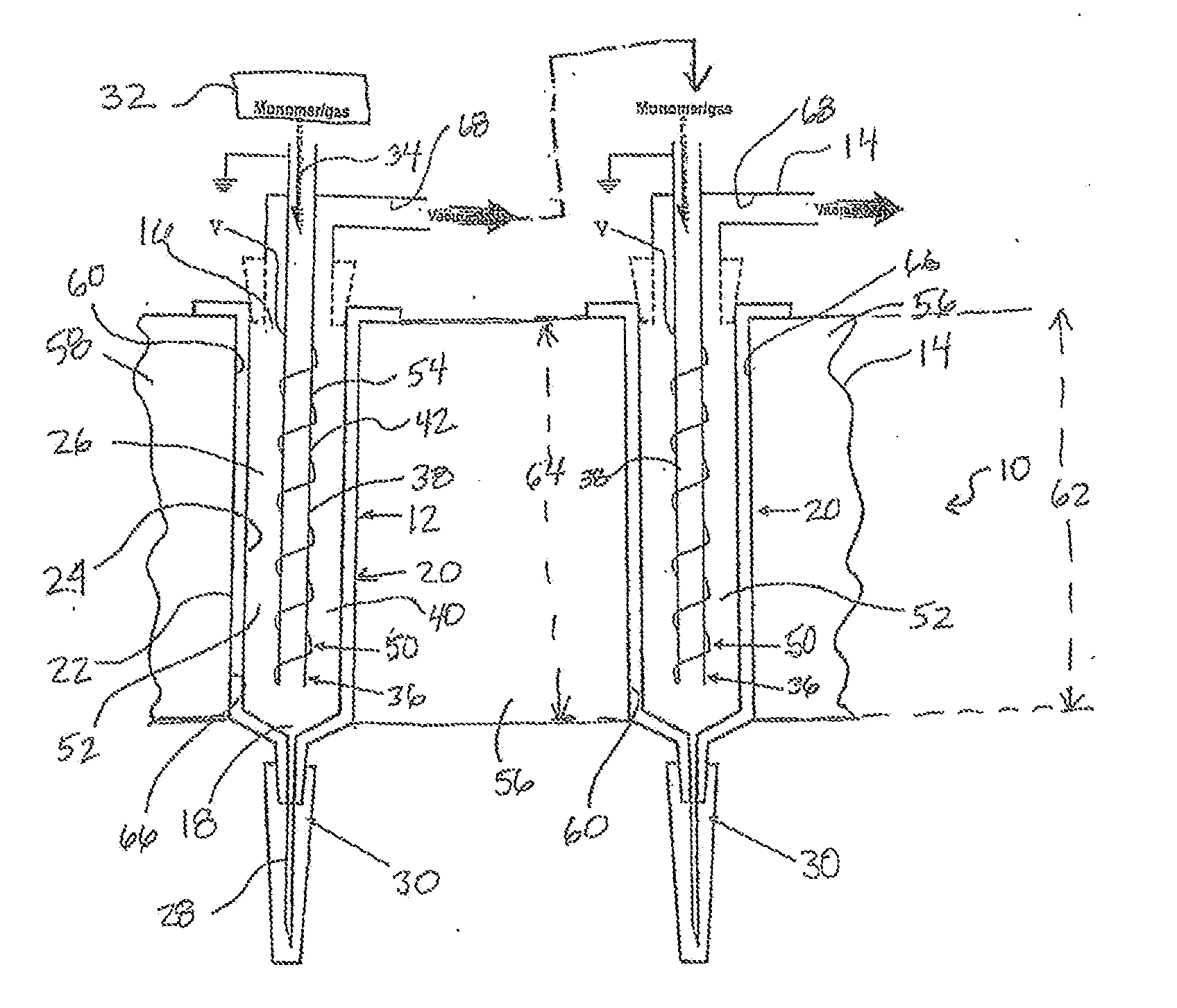
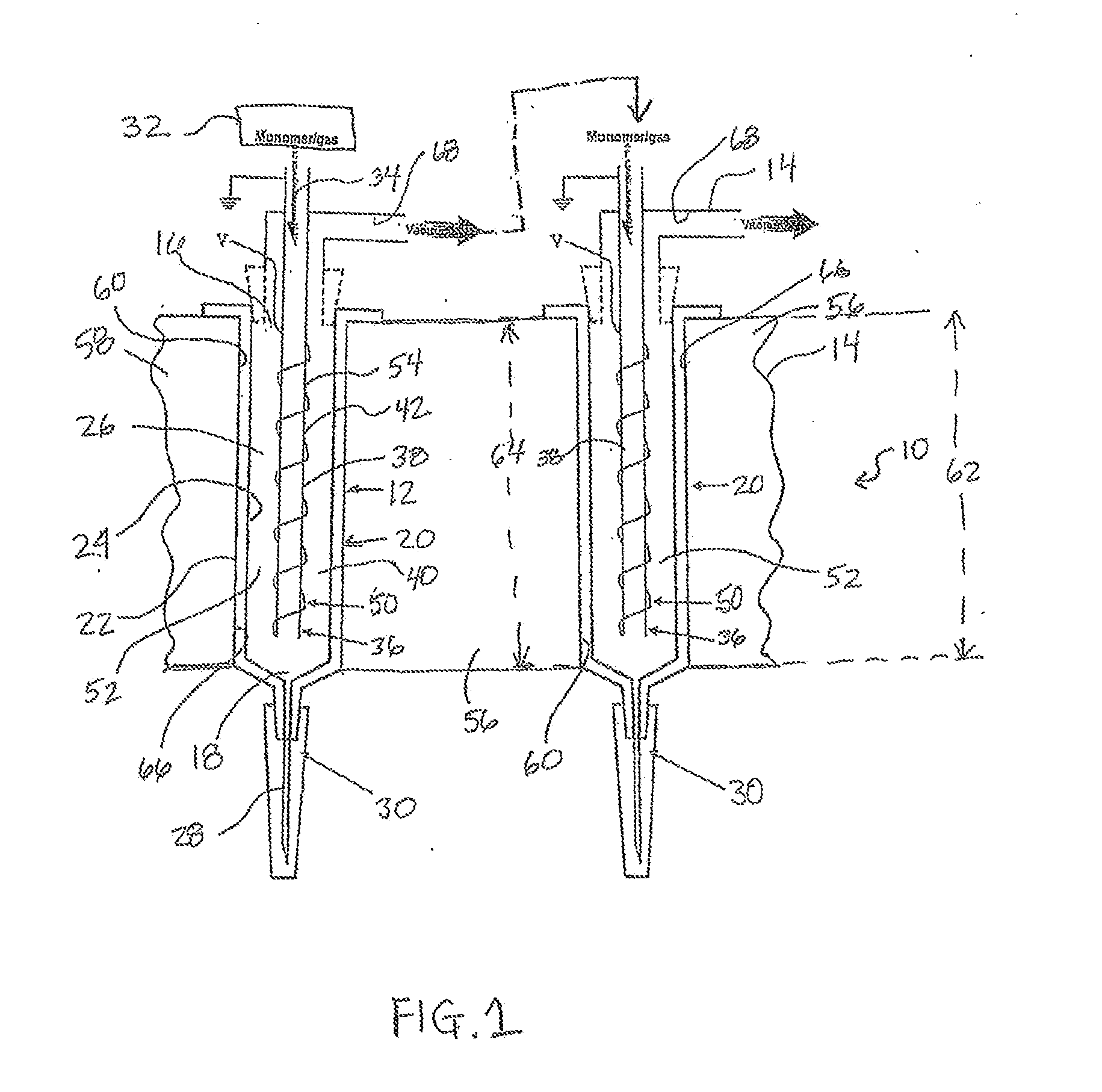
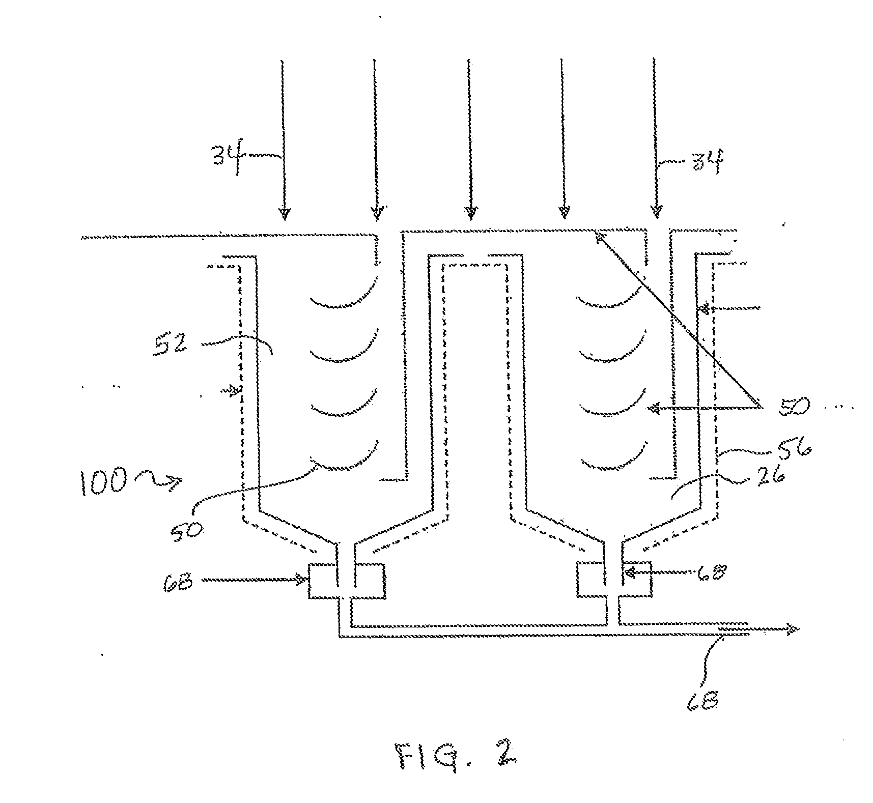
The present invention provides a system and method for coating the interior wall surface of a container with a film coating. The system includes a monomer gas supply source, a gas inlet duct for supplying monomer gas into the container, a pyrolyzing surface for pyrolyzing the monomer gas to form a reactive gas, a temperature controller for maintaining the interior wall surface of the container at a lower temperature to facilitate deposition and polymerization of the reactive gas, and an outlet duct for removing excess reactive gas. The method involves positioning the gas inlet duct at the open end of the container and pyrolyzing the monomer gas to form a reactive gas, which is then maintained at a lower temperature to facilitate deposition and polymerization of the reactive gas on the interior wall surface of the container. The technical effect of this invention is to provide a system and method for coating the interior wall surface of a container with a film coating that is efficient and effective.

Problems solved by technology

However, glass containers can be fragile and expensive to manufacture.
However, polymeric containers can be permeable to gases, permitting atmospheric gases to pass through the polymeric container to the packaged product and also permitting gases in the packaged product to escape through the polymeric container, both of which undesirably degrade the quality and shelf life of the packaged product.
However, such an approach is relatively complicated and costly.
Whether the container is formed from glass or polymeric material, reactivity of the interior surface of the container with the contents of the container, such as biological materials and / or drugs, can be problematic.
However, it can be difficult to obtain a uniform barrier coating, particularly on the interior of containers of small volume and complex interior design, for example syringe barrels.
Also, certain devices, such as syringe barrels, require slow and controlled initiation and maintenance of sliding movement of one surface over another surface.
Breakout and breakloose forces are particularly troublesome in liquid dispensing devices, such as syringes, used to deliver small, accurately measured quantities of a liquid by smooth incremental line to line advancement of one surface over a second surface.
The problem is also encountered in devices using stopcocks, such as burets, pipets, addition funnels, and the like where careful dropwise control of flow is desired.
The problems of excessive breakout and breakloose forces are related to friction.
Such products have the disadvantage of being soluble in a variety of fluids, such as vehicles commonly used to dispense medicaments.
In addition, these lubricants are subject to air oxidation resulting in viscosity changes and objectionable color development.
Further, they are particularly likely to migrate from the surface to surface interface.
Polytetrafluoroethylene surfaces provide some reduction in breakout and / or breakloose forces, but this material is very expensive, and the approach has not been totally effective.

Method used


Image

  • Systems, Apparatus and Methods for Coating the Interior of a Container Using a Photolysis and/or Thermal Chemical Vapor Deposition Process
  • Systems, Apparatus and Methods for Coating the Interior of a Container Using a Photolysis and/or Thermal Chemical Vapor Deposition Process
  • Systems, Apparatus and Methods for Coating the Interior of a Container Using a Photolysis and/or Thermal Chemical Vapor Deposition Process

Examples


Embodiment Construction

[0038]Other than in the operating examples, or where otherwise indicated, all numbers expressing quantities of ingredients, reaction conditions, and so forth used in the specification and claims are to be understood as being modified in all instances by the term “about”. Accordingly, unless indicated to the contrary, the numerical parameters set forth in the following specification and attached claims are approximations that may vary depending upon the desired properties sought to be obtained by the present invention. At the very least, and not as an attempt to limit the application of the doctrine of equivalents to the scope of the claims, each numerical parameter should at least be construed in light of the number of reported significant digits and by applying ordinary rounding techniques.

[0039]Notwithstanding that the numerical ranges and parameters setting forth the broad scope of the invention are approximations, the numerical values set forth in the specific examples are repor...


PUM

PropertyMeasurementUnit
temperatureaaaaaaaaaa
lengthaaaaaaaaaa
inner diameteraaaaaaaaaa

Abstract

Systems, apparatus and methods are provided to apply barrier and / or lubricant materials onto the interior surface of a container, such systems including a container having a chamber; a gas supply source for supplying monomer gas through a gas inlet duct having a portion extending into the chamber; a photolysis source and / or pyrolyzing surface for photolyzing and / or pyrolyzing at least a portion of the monomer gas to form a reactive gas comprising at least one reactive moiety; optionally a temperature controller for maintaining the interior surface of the container at a temperature which is less than the temperature of the pyrolyzing surface to facilitate deposition and polymerization of the reactive moiety on the interior surface of the container; and an outlet duct at the open end or a second end of the container for removing excess reactive gas from the chamber.

Description

CROSS-REFERENCE TO RELATED APPLICATION[0001]This application claims the benefit of U.S. Provisional Patent Application Ser. No. 61 / 192,782, filed on Sep. 22, 2008, incorporated by reference herein in its entirety.BACKGROUND OF THE INVENTION[0002]1. Field of the Invention[0003]This invention relates to systems, apparatus and methods for photolysis and / or thermal chemical vapor deposition (CVD), such as pyrolyzing hot filament CVD (HFCVD), to provide barrier and / or lubricant coating(s) on the interior surface of a container, such as a syringe, tube or medical collection device.[0004]2. Description of Related Art[0005]Traditionally, containers for chemically sensitive materials have been made from inorganic materials such as glass. Glass containers offer the advantage that they are substantially impenetrable by atmospheric gases and thus provide a product with a long shelf life. However, glass containers can be fragile and expensive to manufacture.[0006]More recently, lighter and less ...

Claims


Application Information

Patent Timeline
Patent Type & Authority Applications(United States)
IPC IPC(8): B65D39/00C23C16/448C23C16/455C23C16/52
CPCA61M5/3129A61M2005/3131C23C16/401B05D7/22C23C16/045B05D1/60C23C16/30C23C16/48C23C16/483
Inventor RODRIGUEZ SAN JUAN, NESTORSRIDHARAN, SRINIVASAN
Owner BECTON DICKINSON & CO
Learn More