
Punch Press

a punch press and punch technology, applied in the field of punch presses, can solve the problems of not being able to interchange the male punch and female punch of many prior art punch presses with other die sets, not being able to adjust, and not being able to recognize the configuration of prior art punch presses

Inactive Publication Date: 2011-08-04
BLAIR JASON
View PDF34 Cites 6 Cited by
  • Summary
  • Abstract
  • Description
  • Claims
  • Application Information

AI Technical Summary

Benefits of technology

[0010]It is an object of the invention to provide an improved punch press that reduces the disadvantages of prior art punch presses.
[0014]It is another object of the invention to provide an improved punch press that is versatile in its applications.

Problems solved by technology

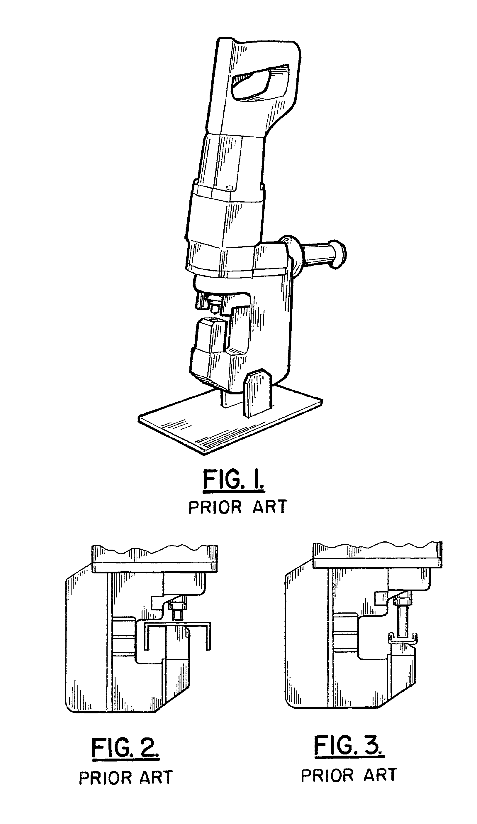
Although a typical prior art punch press is able to create center holes in single-struts and single-shallow-struts, the inventor is not aware of a prior art punch press that is configured to create side holes in single-struts or double-struts.
Furthermore, the inventor is not aware of a prior art punch press that is configured to create center holes in a single-deep strut, a double-strut, or a double-shallow strut.
And although the male punch and female die are removable components, their positioning on the punch press is pre-set, and not adjustable.
Furthermore, the male punch and female die of many prior art punch presses are not interchangeable with other die sets.
As a result, a typical prior art punch press does not confer flexibility in what type of applications it can be used in.
As discussed above, a typical prior art punch press is only configured to accept single-struts and single-shallow struts as work pieces, and even then, it is only capable of creating center holes in these type of struts.
As a result of the above-discussed shortcomings of prior art press punches, their use is of a limited benefit to companies in the construction and electrical industries.
Thus, if such companies desire to create side holes in any of the variety of struts discussed above, or if they desire to create center holes in any other type of strut beside the single-strut and single-shallow strut, then a typical prior art punch press will not be suitable for such purposes.
In such scenarios, these companies are then forced to expend a vast amount of money, labor, and time to mechanically or automatically drill holes on site.

Method used


Image

  • Punch Press
  • Punch Press
  • Punch Press

Examples


Embodiment Construction

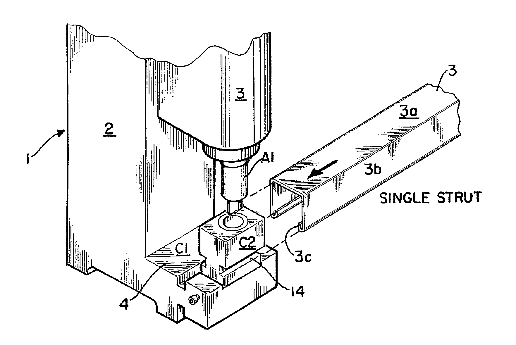
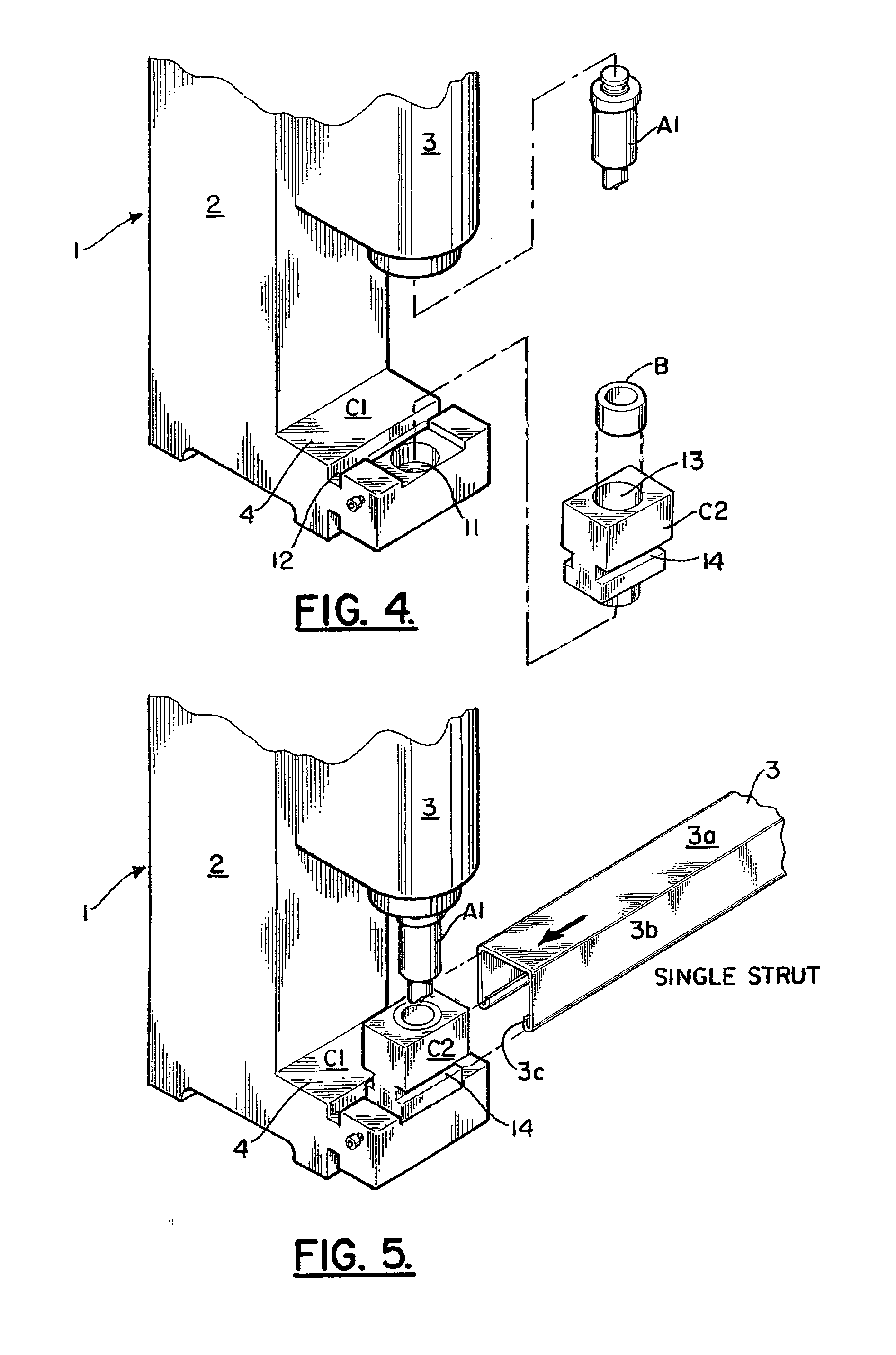
[0023]As depicted by FIGS. 4-12, an improved punch press 1 is disclosed. The improved punch press 1 of the present invention is configured to form or punch center and side holes in a work piece. In a preferred embodiment, the work piece will comprise a strut 3. Strut 3 in turn will comprise a base 3a and two side walls 3b extending from base 3a. Side walls 3b in turn will comprise inward curving lips 3c. As will be discussed further below, punch press 1 is capable of being utilized with a variety of struts 3.

[0024]The inventor contemplates that punch press 1 of the present invention may be manually controlled, numerically controlled through a computer (CNC), or hydraulically and / or electrically operated. A detailed construction of the components of punch press 1 will not be provided, as the general components of punch presses are well known in the art. However, a preferred embodiment of the basic and unique components of punch press 1 will be discussed.

[0025]In a preferred embodimen...


PUM

PropertyMeasurementUnit
Lengthaaaaaaaaaa
Diameteraaaaaaaaaa

Abstract

An improved and efficient punch press comprising a unique assembly of adjustable and interchangeable components to offer a device that is versatile in its applications.

Description

BACKGROUND OF THE INVENTION[0001]1. Field of the Invention[0002]This invention relates to punch presses in general, and more particularly, to an improved and versatile punch press comprising a unique assembly of movable, adjustable, and interchangeable parts.[0003]2. Prior Art[0004]Punch presses are well known in the prior art for forming and cutting metal work pieces. A variety of punch presses exist in the prior art. Punch presses may be manually controlled, numerically controlled through a computer (CNC), or hydraulically and / or electrically operated. Punch presses in general comprise a die set. A die set in turn includes a male punch and a female die. At the beginning of the punching process, the male punch is temporality affixed to the end of a ram configured to move in a vertically linear manner. The female die is situated in a table or work bed. A work piece is positioned between the male punch and the female die. To initiate the punching sequence, the ram is moved downward, ...

Claims


Application Information

Patent Timeline
IPC IPC(8): B26F1/14
CPCB21D28/243Y10T83/9425
Inventor BLAIR, JASON
Owner BLAIR JASON
Learn More