
Stapling apparatus for performing anastomosis on hollow organs

Active Publication Date: 2011-07-28
ZAKEASE SURGICAL
View PDF19 Cites 22 Cited by
  • Summary
  • Abstract
  • Description
  • Claims
  • Application Information

AI Technical Summary

Benefits of technology

[0010]The L-shaped configuration of the clip retainer tool and of the staple retainer tool provides exceptional unobstructed access and visibility of the anastomosis surgical site, and this same L-shaped configuration of the tool further permits ensured firing of all staples by the ability to apply simultaneous downward engagement of the top ends of all the staple heads by a firing mechanism.

Problems solved by technology

Microvascular anastomosis is generally performed by hand under a microscope, and is tedious and painstaking work.
As a result, it can take many hours to complete just the microvascular anastomosis required to reconnect a severed body part or transplant an organ.
In such surgical procedures, speed of performing the operation can become extremely critical.

Method used


Image

  • Stapling apparatus for performing anastomosis on hollow organs
  • Stapling apparatus for performing anastomosis on hollow organs
  • Stapling apparatus for performing anastomosis on hollow organs

Examples


Embodiment Construction

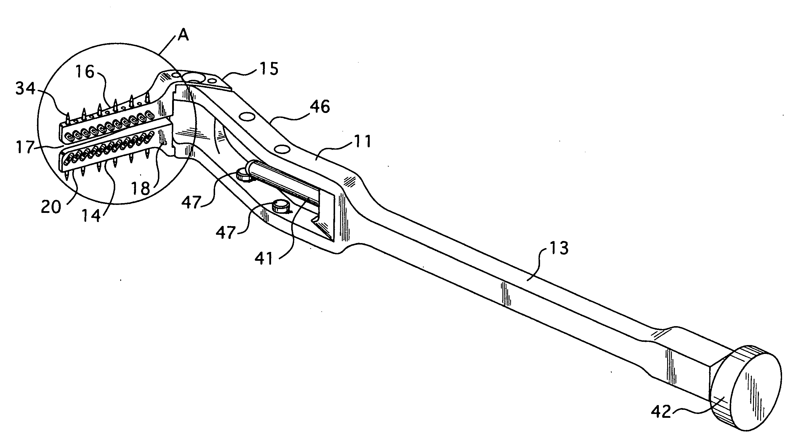
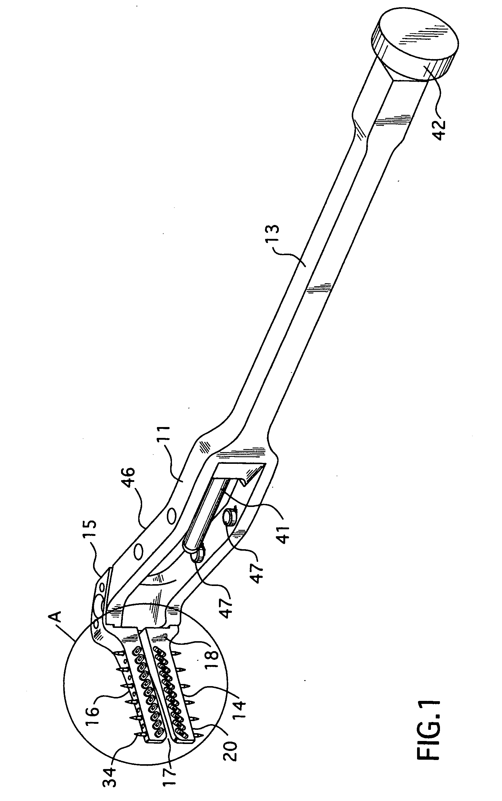
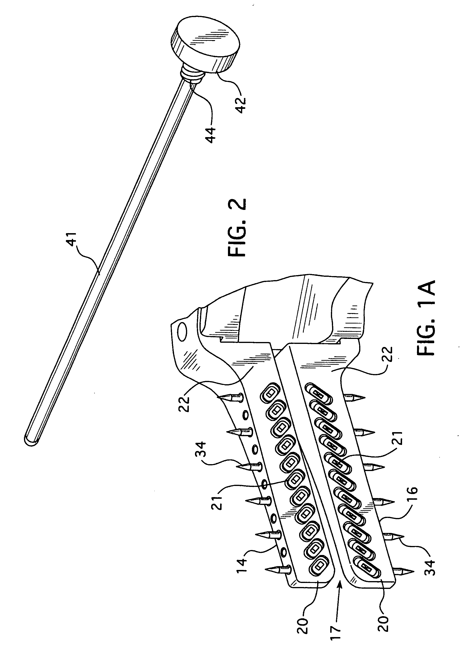
[0037]Referring to FIGS. 1 through 17, the anastomosis stapling apparatus 10 of the present invention is shown in its complete combined form in FIGS. 7 through 14. The stapling apparatus 10 is comprised of two separate combinable tools in the form of L-shaped clip retainer tool 11 and L-shaped staple retainer tool 12. Describing first the L-shaped clip retainer tool 11 shown in FIGS. 1 and 1A, the clip retainer tool 11 includes an elongated clip retainer handle 13 with a clip retaining foot 14 extending laterally from bottom distal end 15 of handle 13. Clip retaining foot 14 is comprised of a C-shaped clip jaw 16 which is positioned in a plane that is substantially transverse to the clip retainer handle 13 as illustrated in FIG. 1. C-shaped clip jaw 16 defines an organ exit gap 17 for removal of stapled hollow organ ends after stapling as will be explained in greater detail hereinafter.

[0038]Side face 18 of C-shaped clip jaw 16 provides an upwardly facing top face 22. Clip retainer ...


PUM

PropertyMeasurementUnit
Pressureaaaaaaaaaa

Abstract

A stapling apparatus for performing anastomosis on hollow organs. The apparatus consists of two combinable tools which are L-shaped, one tool for retaining staple retaining clips, and the other tool for retaining staples. The L-shaped tools are each provided with an elongated handle and a C-shaped jaw positioned at a distal bottom end of the handle in a plane substantially transverse to the handles of the tools. When the two tools are combined, the C-shaped jaw retaining a series of staple retaining clips is positioned below the C-shaped jaw retaining the arranged series of staples with the respective staples in registration with respective underlying clips for stapling. The C-shaped jaws provide gaps which permit ingress and egress of hollow organ ends to be stapled. A staple firing mechanism is operated from the proximal top end of one of the handles of the stapling apparatus whereby downward pressures is applied uniformly and simultaneously against the top of all staples to force them from their retaining sockets, through the hollow organ ends, and into stapling engagement with the respective underlying staple retaining clips.

Description

FIELD OF THE INVENTION[0001]The present invention pertains to the field of medicine and more particularly to surgery. More specifically, the present invention generally relates to surgical suturing devices and methods for applying anastomosis onto hollow organs, e.g. the organs of the digestive tract or blood vessels, for instance, for joining them together in end-to-end or end-to-side utilizing fastener securing techniques.BACKGROUND OF THE INVENTION[0002]End-to-end anastomosis is a surgical procedure for connecting an end of one hollow organ to an end of another hollow organ. End-to-end anastomosis is commonly performed on vascular and / or visceral tissue. Microvascular anastomosis is generally performed to make ends of blood vessels in the course of, for example, reattaching severed body parts and / or transplanting organs. Microvascular anastomosis is generally performed by hand under a microscope, and is tedious and painstaking work. As a result, it can take many hours to complete...

Claims


Application Information

Patent Timeline
IPC IPC(8): A61B17/115
CPCA61B17/0643A61B17/1152A61B2017/1132A61B2017/0647A61B17/1155
Inventor TZAKIS, ANDREASMORELLI, JAMESSADOWSKI, DANIEL
Owner ZAKEASE SURGICAL
Learn More