
Device for fixing screws in osteoporotic bones

Inactive Publication Date: 2011-07-28
VEME MEDICO QUIRURGICA SL
View PDF10 Cites 10 Cited by
  • Summary
  • Abstract
  • Description
  • Claims
  • Application Information

AI Technical Summary

Benefits of technology

[0033]The present invention has the advantage over others previously described that the threading inside the biocompatible element assuring the fixing of the screw is carried out at the time of introducing same. Since it is previously drilled and is preferably made of plastic material, the use of a threading prior to introducing the screw will generally not be necessary, given that the thread will be created by the advance of the screw itself inside the fixing element. This will allow the use of any type of screw in all the fixing elements, which considerably reduces the cost of the manufacturing and use process.
[0034]The instrument used to place the fixing el

Problems solved by technology

The fundamental consequence is that bone brittleness and, therefore, the possibilities of fractures with even banal traumas, increase.
Unfortunately, the loss of bone mass conditions the fixing of the screws being deficient, therefore it is frequent for such screws to give way with the mechanical stressing of the bone in which they are implanted and to be detached from it.
The immediate consequence will be the loss of stability in the focal point of the fracture with all the complications that this entails.
In the same way, in bone fractures in young individuals the screws frequently traverse lines or fissures of the bone, in which the fixing is impossible as such screws do not achieve sufficient hold.
The main technical difficulty lies in how to place a fragment of one of these materials so that it is traversed by the screw after the latter has passed the two bone cortices and assure the grip in said fragment.
Likewise, a problem which must be solved is the shape and dimensions that said parts must have to prevent them from penetrating the bone cortex due to the pressures generated on such parts.

Method used


Image

  • Device for fixing screws in osteoporotic bones
  • Device for fixing screws in osteoporotic bones
  • Device for fixing screws in osteoporotic bones

Examples


Embodiment Construction

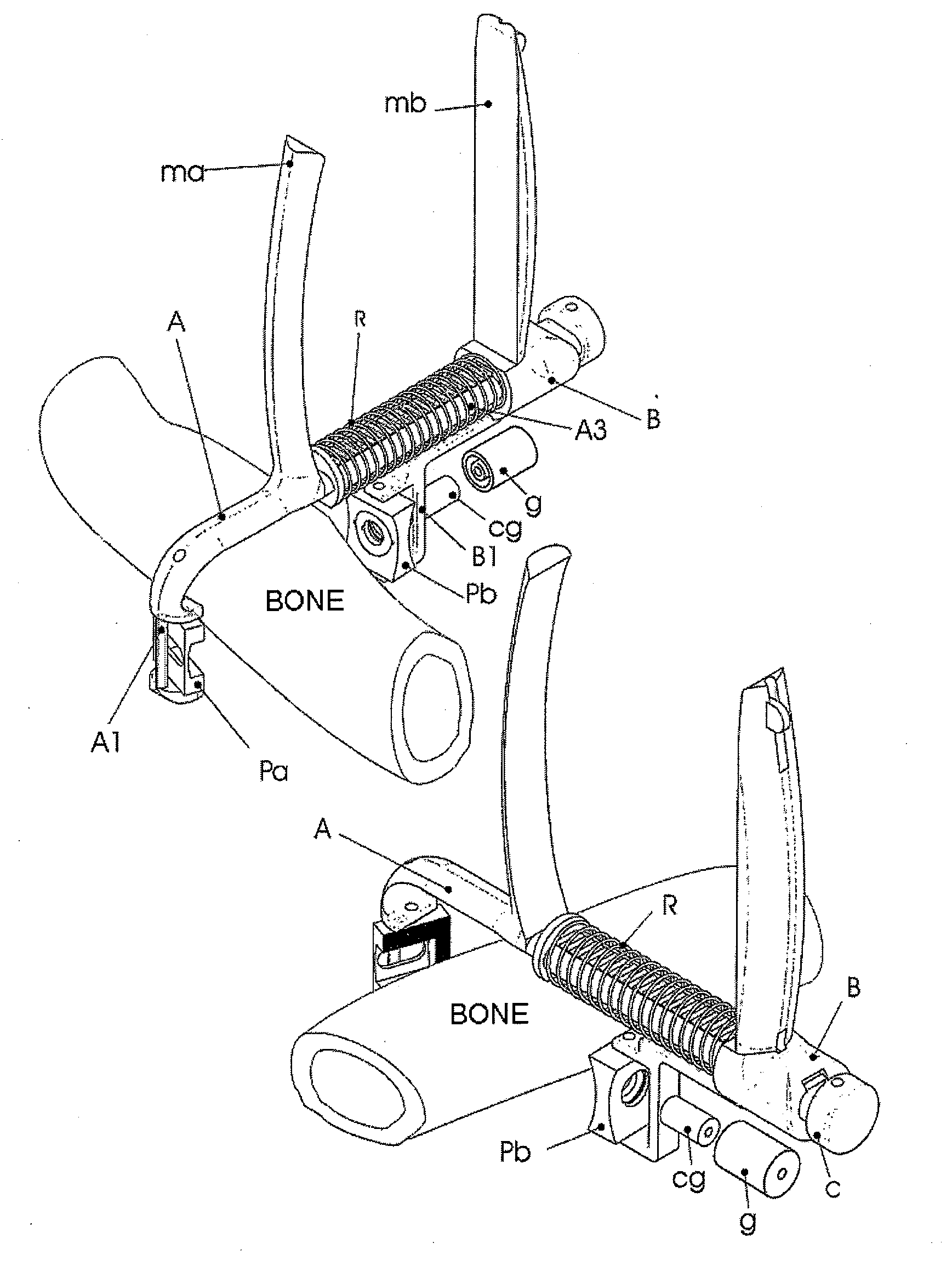
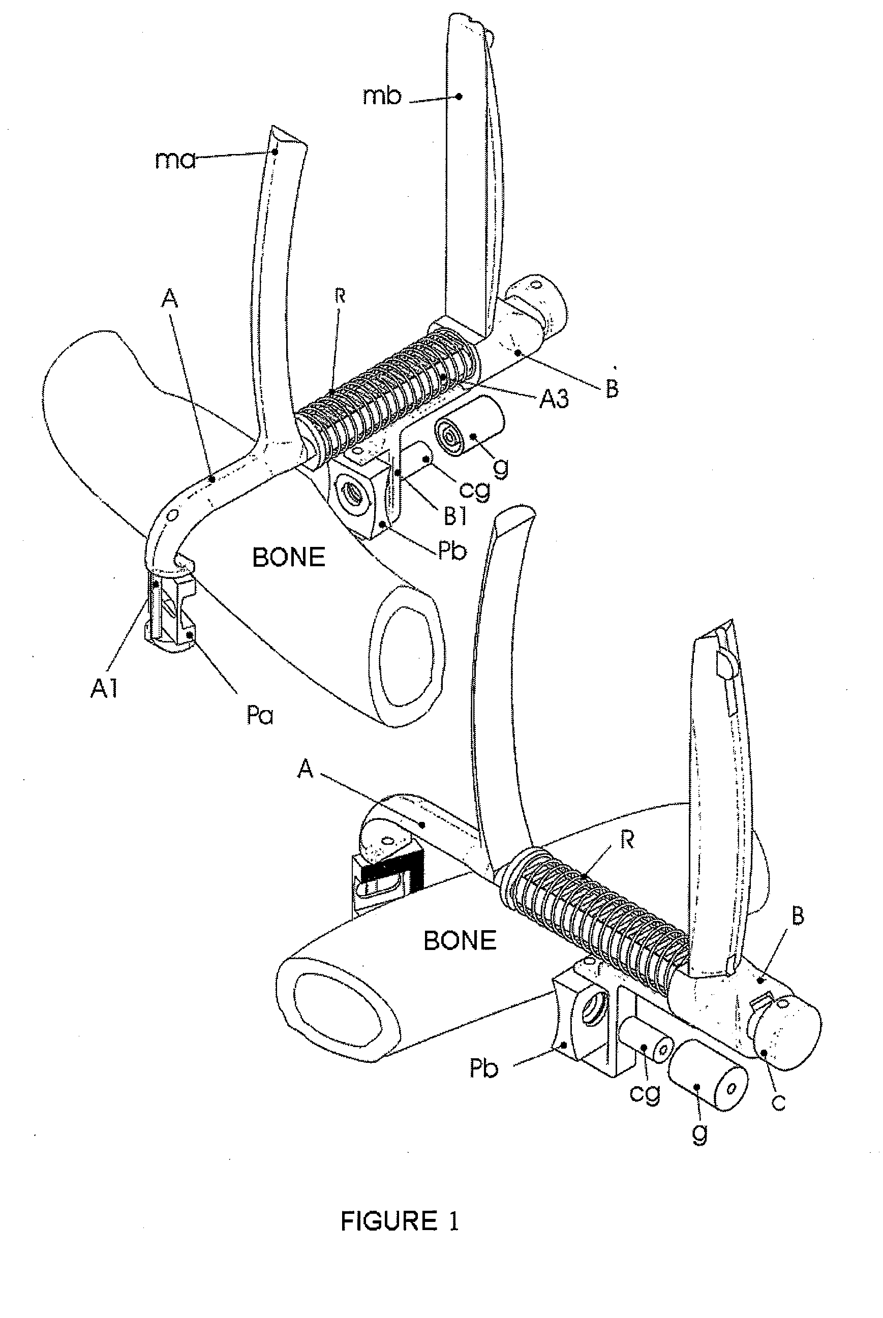
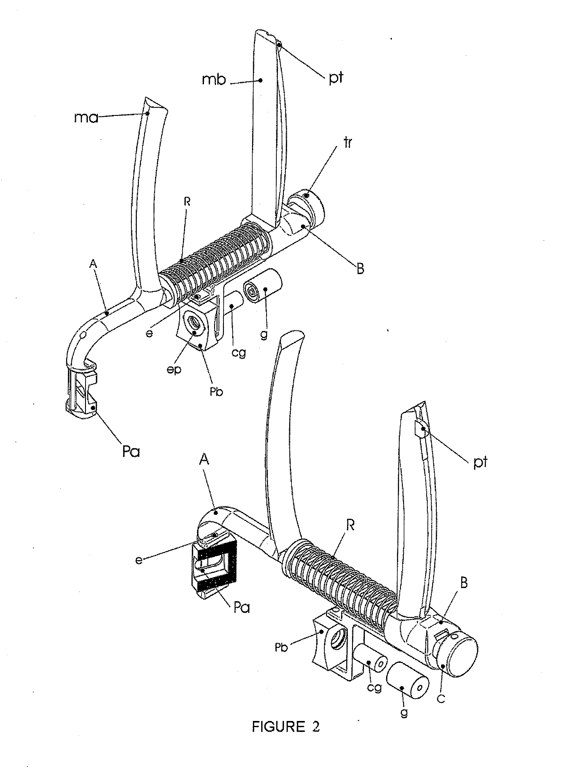
[0008]The device for fixing screws in osteoporotic bones is formed by biocompatible laminar elements assuring the fixing of the screw once the latter has traversed the structure thereof and an instrument facilitating the placement of said elements in the areas of the bone opposite that of the incision, by means of the handling from the side of the cut. The purpose is that said biocompatible material serves for securing the end of the threaded stem of the screw and prevents its loosening. Likewise, the device for fixing screws in osteoporotic bones facilitates the placement of washers or plates on the side of the incision, simultaneously to the fixing of the lamina elements in the face opposite that of the incision.

[0009]The instrument used in placing the biocompatible elements for fixing screws in osteoporotic bones is formed by two basic parts, a male part and another female part, connected to one another by a momentum of surface contact, relative linear sliding movement and a degr...


PUM


Abstract

The invention relates to a device for fixing screws in osteoporotic bones, formed by biocompatible fixing elements and an instrument for placing same. The instrument consists of two parts, a male part (A) and a female part (B), which can perform a relative linear sliding movement. The caudal end of each part has a pivoting jaw (Pa, Pb) forming an inverted U therebetween. The biocompatible element is placed in the jaw of the male part, which element will be traversed by a screw inserted through interchangeable guides (g) placed in the other jaw, acting as a locking and fixing nut for said screw. Both parts have a handle (m) to allow moving the jaws closer together. The opening of the device, restricted by a closure (C), is achieved by the action of a compression spring (R), upon releasing, by the action of the thumb, the catch inserted in the upper face, cut in a saw-toothed manner, of part A.

Description

[0001]The present invention relates to a device facilitating the fixing in osteoporotic bones of screws normally used in the osteosynthesis of non-pathological bones. The device in question consists of a biocompatible element and an instrument which is used to handle it, which will act as a fixing nut after being traversed by the screw which has previously passed the bone cortices, thus providing a higher tensile strength of the threaded attachment.BACKGROUND OF THE INVENTION[0002]Millions of people suffer from osteoporosis, a typical disease of the elderly, in which the bone loses density. The fundamental consequence is that bone brittleness and, therefore, the possibilities of fractures with even banal traumas, increase. Once the fracture occurs, the use of plates and screws for fixing the bone fragments in a correct alignment, while at the same time the mobilization of the adjacent joints is allowed, is required most of the time. Unfortunately, the loss of bone mass conditions th...

Claims


Application Information

Patent Timeline
IPC IPC(8): A61B17/56
CPCA61B17/1728A61B17/8872A61B17/808A61B17/80
Inventor GARCES MARTIN, GERARDOCARTA GONZALEZ, JOSE ANTONIOYANEZ SANTANA, ALEJANDRO
Owner VEME MEDICO QUIRURGICA SL
Learn More