
Control system of hybrid power drive apparatus

a control system and hybrid technology, applied in the direction of machines/engines, vehicle sub-unit features, gearing, etc., can solve the problems of increasing fuel consumption and loss of drive power

Inactive Publication Date: 2011-07-21
AISIN AI CO LTD +2
View PDF3 Cites 13 Cited by
  • Summary
  • Abstract
  • Description
  • Claims
  • Application Information

AI Technical Summary

Benefits of technology

The technical problem addressed in this patent is the increase in fuel consumption and loss of drive power in an automotive vehicle equipped with a hybrid drive power apparatus when the temperature of the lubricant in the transmission housing drops during parking of the vehicle for a long time. This is due to high viscosity of the lubricant immediately after start of the vehicle.

Problems solved by technology

In an automotive vehicle equipped with the hybrid drive power apparatus, when the temperature of lubricant in the transmission housing dropped during parking of the vehicle for a long time, stirring resistance of the lubricant increases due to high viscosity of the lubricant immediately after start of the vehicle, resulting in loss of the drive power and increase of fuel consumption.

Method used


Image

  • Control system of hybrid power drive apparatus
  • Control system of hybrid power drive apparatus
  • Control system of hybrid power drive apparatus

Examples


Embodiment Construction

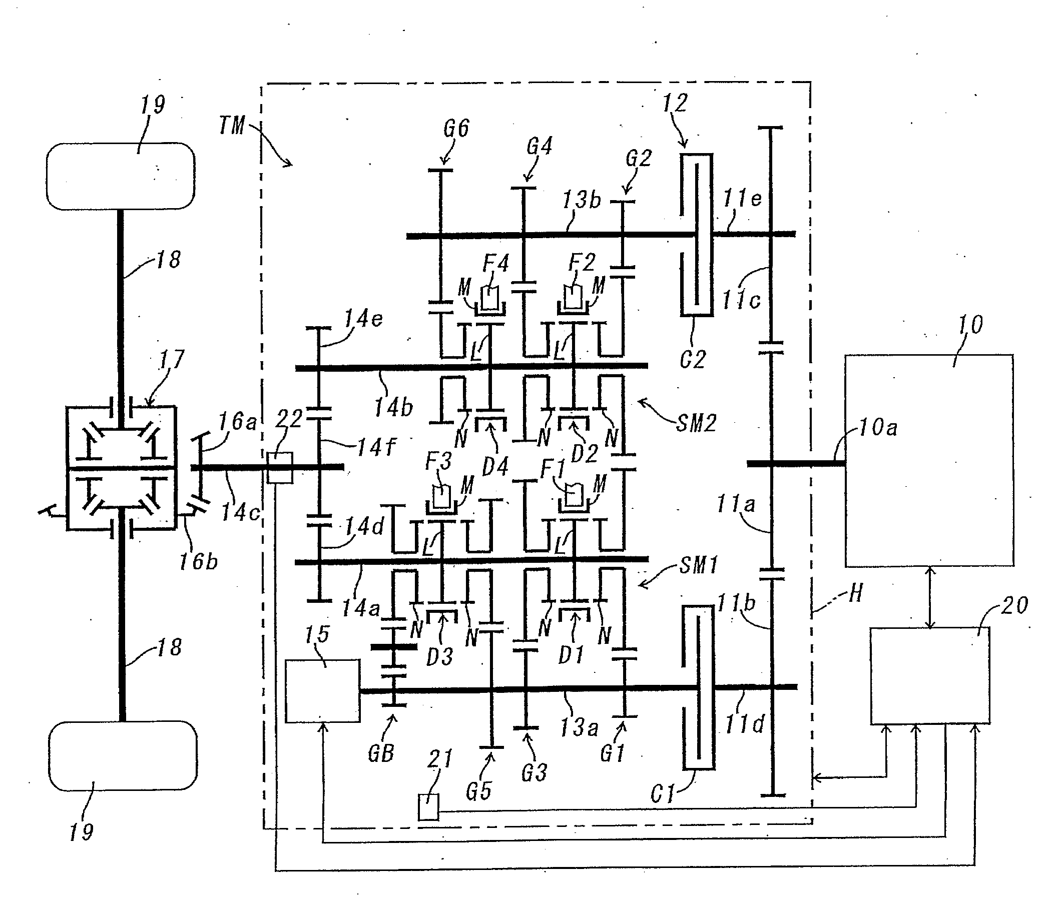
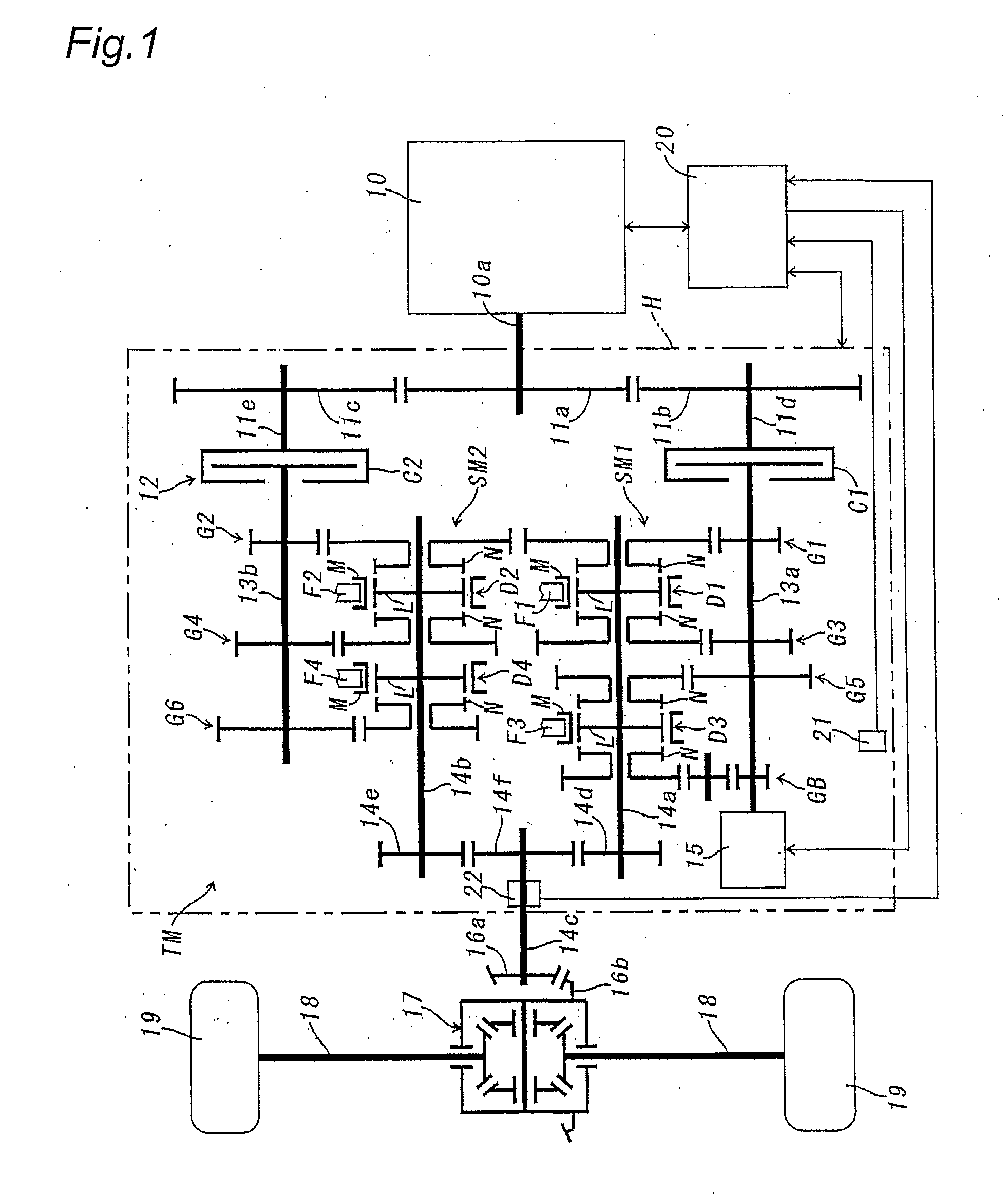
Hereinafter, an embodiment of a hybrid drive power apparatus according to the present invention will be described with reference to FIGS. 1˜4. In this embodiment, the hybrid drive power apparatus is adapted to an automatic power transmission TM of forward six speed steps and a backward step as shown in FIG. 1.

The automatic power transmission TM is in the form of a gear transmission of the dual-clutch type wherein a first input shaft 13a and a second input shaft 13b are rotatably mounted in parallel within a transmission housing H and drivingly connected to an output shaft 10a of an engine 10 through a first friction clutch C1 and a second friction clutch C2. An input member of first friction clutch C1 is connected to a support shaft 11d of a driven gear 11b in mesh with a drive gear 11 a for rotation with the output shaft 10a of engine 10. Similarly, an input member of friction clutch C2 is connected to a support shaft 11e of a driven gear 11c in mesh with the drive gear 11 a for ro...


PUM


Abstract

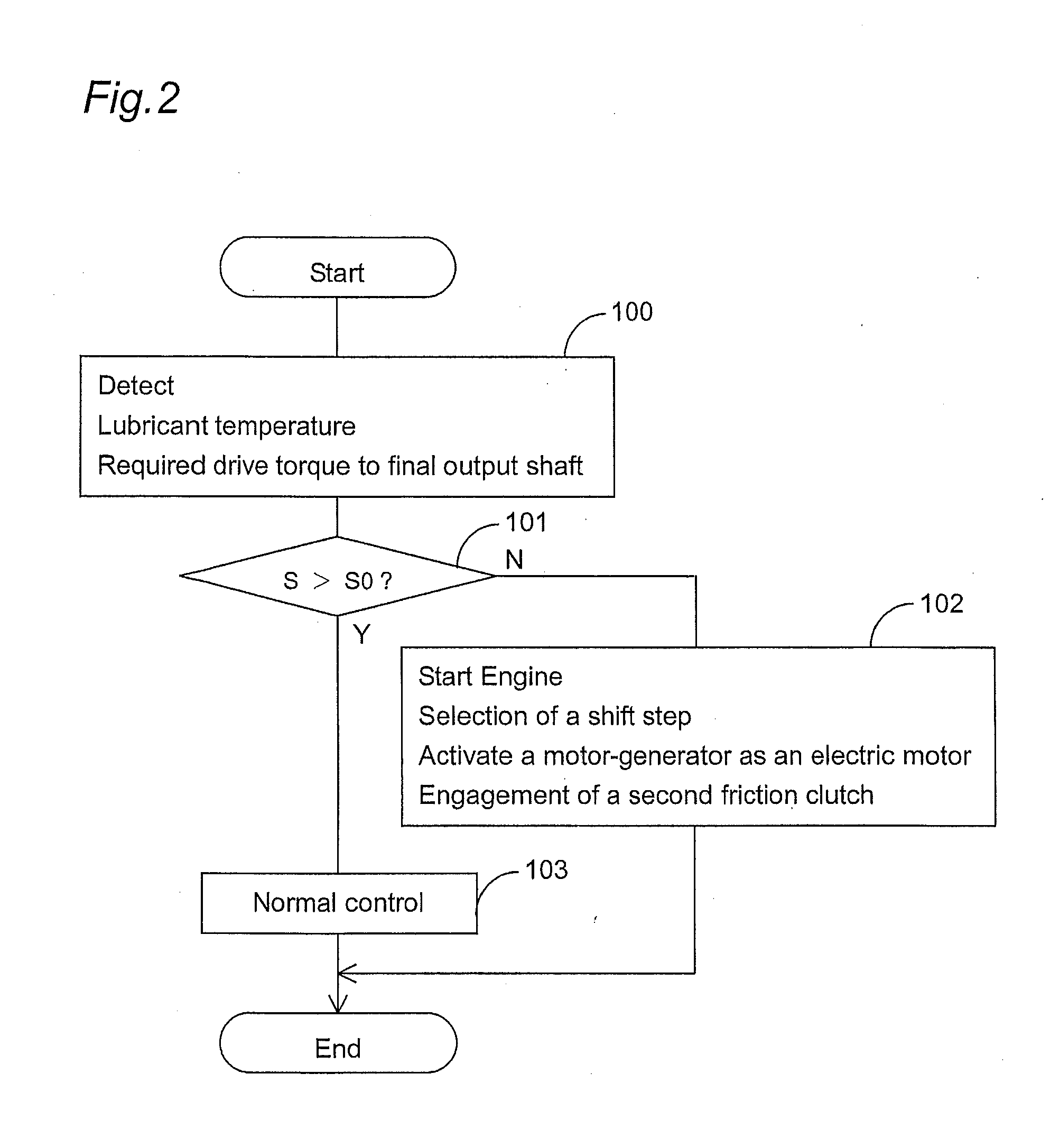
[Subject]To rapidly rise a temperature of lubricant in a transmission housing of a hybrid drive power apparatus when the lubricant temperature is lower than a preset lower limit value.[Solution]A control system of a hybrid drive power apparatus of the type which comprises a transmission housing provided therein with a first input shaft to be applied with drive power from an engine through a first friction clutch and a second input shaft to be applied with the drive power of the engine through a second friction clutch, first and second gear-shift mechanisms respectively assembled with the first and second input shafts, a final output shaft in drive connection with each output shaft of the gear-shift mechanisms, a motor-generator in drive connection with the first input shaft or the second input shaft, and a driven mechanism in drive connection with the final output shaft, wherein the control system includes a temperature sensor for detecting a temperature of lubricant stored in the transmission housing, and control means for selecting a shift-step in the first or second gear-shift mechanism assembled with the input shaft in drive connection with the motor-generator when the lubricant temperature detected by the sensor is lower than a preset lower limit value so that drive torque larger than that required for driving the driven mechanism is transferred to the final output shaft, for activating the motor-generator as an electric motor after selection of the shift-step , and for engaging the first or second friction clutch so that the drive torque of the engine is transferred to the final output shaft through a gear set at the selected shift-step in the first or second gear-shift mechanism.

Description

FIELD OF THE INVENTIONThe present invention relates to a hybrid drive power apparatus, particularly to a control system of a hybrid drive power apparatus suitable for applied to a power transmission of the dual-clutch type for rapidly warming lubricant in the transmission housing when the lubricant temperature is low.DISCUSSION OF THE PRIOR ARTDisclosed in Japanese Patent Laid-open Publication No. 2005-186931 is a hybrid drive power apparatus equipped with a power transmission of this type. The hybrid drive power apparatus includes first and second input shafts arranged to be selectively rotated by drive power of an engine transmitted thereto through a dual-clutch, first and second gear-shift mechanisms respectively assembled with first and second output shafts in parallel with the first and second input shafts, and a motor-generator in drive connection with the second output shaft to be activated as an electric motor for driving a set of driven road wheels in drive connection to th...

Claims


Application Information

Patent Timeline
Patent Type & Authority Applications(United States)
IPC IPC(8): B60K6/42B60K6/48B60K6/547B60L50/16B60W10/06B60W10/08B60W10/10B60W20/00F16H3/093F16H59/14F16H59/40F16H59/72F16H61/02F16H61/68F16H61/684F16H61/688F16H63/40F16H63/50
CPCB60K6/36Y02T10/6286B60L2240/485B60L2240/486B60W10/02B60W10/06B60W10/08B60W10/113B60W20/00B60W30/194B60W2510/105B60W2510/107B60Y2400/428F02D29/02F16H3/006F16H3/089F16H57/0413F16H59/72F16H61/688F16H2003/0931F16H2061/0241F16H2200/0052B60K6/547Y02T10/62B60W20/40
Inventor TANBA, TOSHIOFUKUHARA, YUICHISASAKI, KANSATO, HIROSHIOMURA, MASAHIRO
Owner AISIN AI CO LTD
Learn More