Balanced fluid valve

a fluid valve and fluid flux technology, applied in the direction of fluid pressure control, flow control, instruments, etc., can solve the problem that fluid pressure regulators usually need a minimum outlet pressure, and achieve the effect of improving the independency of fluid pressur

Inactive Publication Date: 2011-07-21
ISOMATIC
View PDF10 Cites 14 Cited by
  • Summary
  • Abstract
  • Description
  • Claims
  • Application Information

AI Technical Summary

Benefits of technology

[0009]The object of the invention is therefore to provide for a fluid flux regulating unit, showing an improved independency on fluid pressure.
[0010]It is suggested to design a fluid flux regulating unit, comprising a first fluid port, a second fluid port and a valve means in a way that said valve means comprises at least one fluid pressure balancing means. The fluid flux regulating unit is preferably designed in a way that said one or several fluid pressure balancing means provided are balancing the fluid flux regulating unit essentially completely. This essentially complete balancing can be provided in connection with the first fluid port, the second fluid port or both fluid ports. Each fluid pressure balancing means usually has the effect that the influence of the fluid pressure at the respective port on the valve means is reduced. This way, the fluid flux regulating unit can become essentially independent of the fluid pressure at the first fluid port, the second fluid port, or both.
[0011]Preferably, said valve means comprises at least one moveable valve part, wherein preferably said moveable valve part comprises at least one of said fluid pressure balancing means. Using such a movable valve part, the valve means can be designed in an easy and cost-effective way. The regulation of the fluid flow through the fluid flux regulating unit can be performed by a mechanical opening and closing of an opening, through which the fluid can flow. Furthermore, a leakage proof closing of the valve means can usually be easily achieved. However, pressure influences on the valve means usually stem from pressure influences on the movable valve part. Here, the imposed pressure can a create force, which in turn can lead to a movement of the movable valve part, thus creating an influence of the valve means on the applied fluid pressure. By providing said fluid pressure balancing means in connection with said movable valve part, the described effects can usually easily be accounted for and can be even avoided.

Problems solved by technology

Another problem is that fluid pressure regulators usually need a minimum outlet pressure to completely shut off.

Method used


Image

  • Balanced fluid valve
  • Balanced fluid valve
  • Balanced fluid valve

Examples


Embodiment Construction

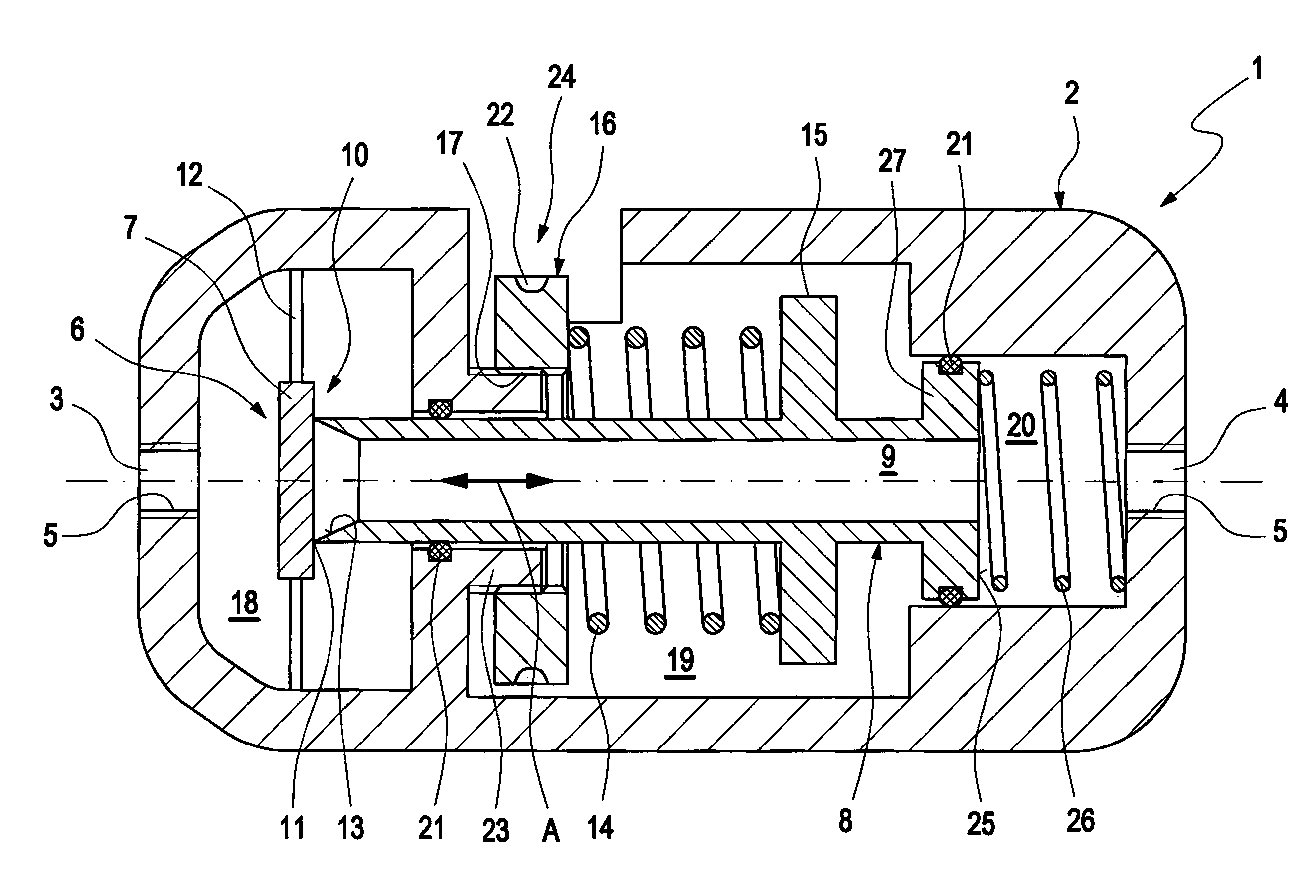
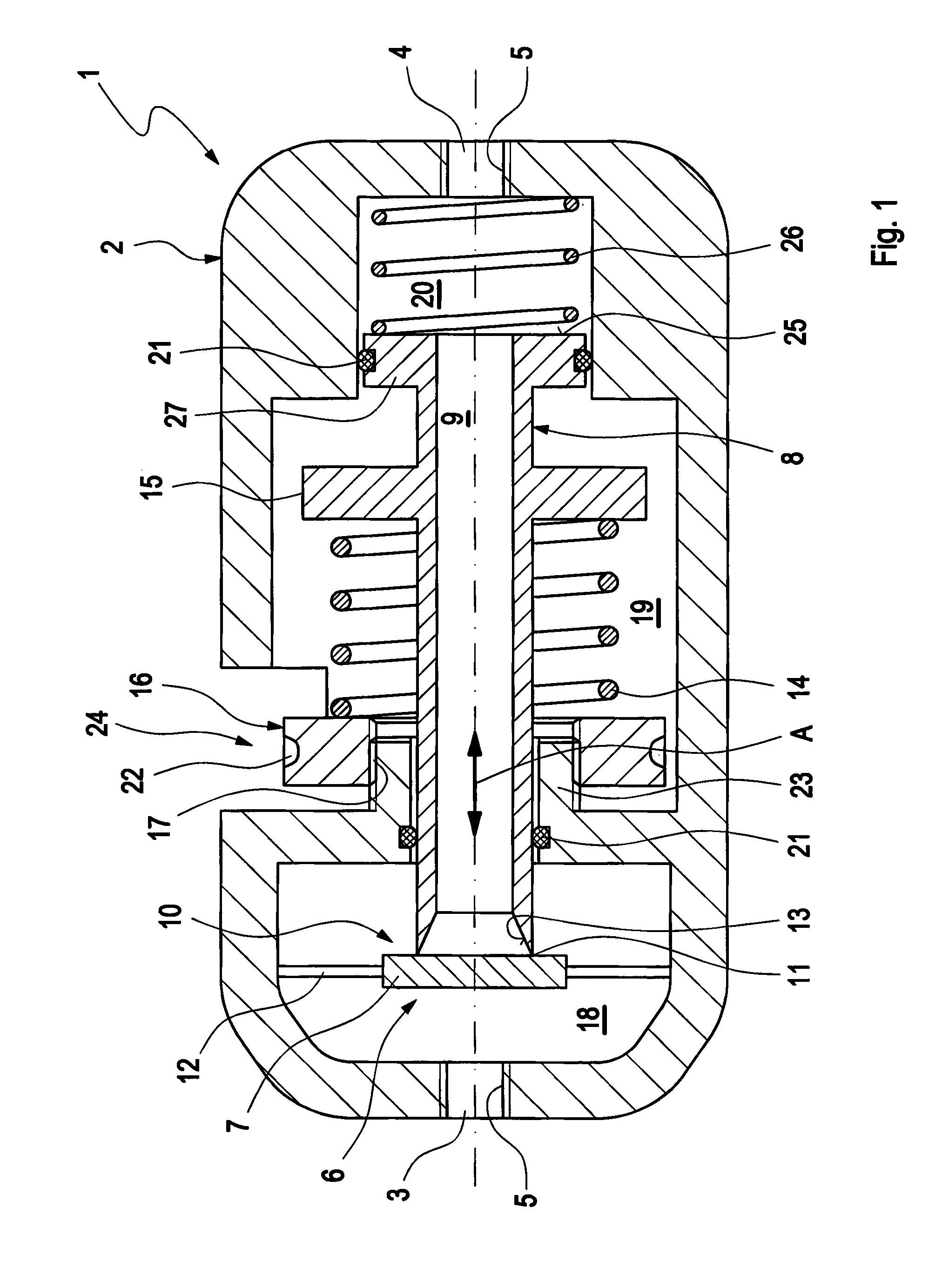
[0035]In FIG. 1, a schematical cross section through a first possible embodiment of a pressure regulator 1 is depicted. The pressure regulator 1 comprises a casing 2 with a fluid inlet port 3 and a fluid outlet port 4. Both fluid inlet port 3 and fluid outlet port 4 have an inner thread 5, so that a corresponding fluid pipe or fluid hose can be threadingly engaged in the respective fluid port 3, 4.

[0036]Within the casing 2 of the pressure regulator 1, a valve unit 6 is arranged. The valve unit 6 essentially consists of a valve seat 7 and a valve tube 8. The valve tube 8 can be moved in an axial direction (as indicated by double-headed arrow A) within the casing 2 of the pressure regulator 1.

[0037]The valve tube 8 is designed to have a hollow interior 9, forming an inner fluid line 9 through the valve tube 8. The contacting area between valve seat 7 and valve tube 8 forms the valve opening 10. If the valve tube 8 is in its leftmost position (as drawn in FIG. 1), the valve seat 7 and ...


PUM


Abstract

It is proposed to design a fluid flux regulating unit (1, 28, 35, 41, 53, 56, 58), comprising a first fluid port (3), a second fluid port (4) and a valve means (6) , in a way that the valve means (6) comprises at least one fluid pressure balancing means (13, 25, 30, 31, 33, 52).

Description

CROSS REFERENCE TO RELATED APPLICATIONS[0001]This application is entitled to the benefit of and incorporates by reference essential subject matter disclosed in International Patent Application No. PCT / DK2009 / 000205 filed on Sep. 17, 2009 and European Patent Application No. 08016556.6 filed on Sep. 19, 2008.FIELD OF THE INVENTION[0002]The invention relates to a fluid flux regulating unit, comprising a first fluid port, a second fluid port and a valve means.BACKGROUND OF THE INVENTION[0003]Fluid flux regulating units are used, when it comes to influencing the amount of fluid flow through a device and / or to influence the direction into which a fluid flow is directed. The influencing behaviour can be based on a variety of parameters, of course. For example, it is possible that a fluid flow is regulated in a way that the fluid pressure in a certain part of a machine is set to a certain pressure, in particular a constant pressure. In other cases, a simple opening and interruption of the f...

Claims


Application Information

Patent Timeline
IPC IPC(8): G05D7/01
CPCG05D7/005G05D7/0133Y10T137/7793Y10T137/7796Y10T137/7798Y10T137/7808Y10T137/7801Y10T137/7797G05D16/106
Inventor KRISTOFFERSEN, SOEREN
Owner ISOMATIC
Why Eureka
Try Eureka