Sail and method of manufacture thereof

a sail and sail technology, applied in the field of sails, can solve problems such as distortion of images, and achieve the effect of high resolution, high resolution, and high resolution

Inactive Publication Date: 2011-07-21
KISS AARON
View PDF23 Cites 0 Cited by
  • Summary
  • Abstract
  • Description
  • Claims
  • Application Information

AI Technical Summary

Benefits of technology

[0007]It is, therefore, one object of the present invention to provide a quality competition sail adorned with high resolution and photorealistic informational matter without compromising performance ability of the racing sail, which may be a Dacron or Mylar-laminated sail. It is another object of the present invention to provide a method for fabricating a quality competition sail that includes and displays high resolution and photorealistic informational matter without compromising performance ability of the racing sail. It is a further object of the present invention to provide a sailboat that includes one or more quality competition sails adorned with high resolution and photorealistic informational matter.
[0013]There is also disclosed herein a novel method for manufacturing a high performance sail. In one embodiment, the method includes: (a) providing a first layer or sheet of clear, white or colored Mylar, Dacron, Taffeta, or other sail material imaged on one side with first informational, graphic and / or other visible content, (b) disposing a first heat-activatable adhesive layer to the other side of the first layer, (c) positioning the first layer on a sail support mechanism or table (e.g. horizontal surface or variable / adjustable three-dimensional mold) with the first adhesive layer facing upwards, (d) positioning a plurality of load bearing yarns upon the first adhesive layer in predetermined load path orientations, (e) providing a second layer or sheet of clear, white or colored Mylar, Dacron, Taffeta, or other sail material imaged on one side with second visible content, (f) disposing a second heat-activatable adhesive layer onto the other side of the second layer (f) positioning the second layer such the second adhesive layer faces the positioned load bearing yarns, wherein at least the first layer, the first adhesive layer, the plurality of load bearing yarns, the second layer and the second adhesive layer form a sail arrangement, (g) positioning the sail arrangement into a vacuum, and (h) applying appropriate heat and pressure to the sail arrangement while the sail arrangement is in the vacuum to activate at least the first and second adhesive layers and to mitigate a quantity of voids within the sail.
[0014]In an alternative embodiment in which the first and second external layers are clear, white, or lightly colored, a darker-colored (e.g., black or charcoal gray) or opaque layer or sheet may be added between the two external layers, if necessary, to substantially reduce the amount of light that can pass through the sail and thereby more effectively prevent the image on the first layer from being seen from the second layer, and vice versa. In such a case, the opaque layer or sheet would be positioned upon the load bearing yarns. Further, one or more additional layers of heat-activatable adhesive may be affixed or disposed upon one or both sides of the opaque layer to enable the opaque layer to attach to the two external layers and the load bearing yarns. The yarns can be comprised of Carbon Fiber, Spectra, Nylon, Kevlar, Mylar and other natural and polymeric fibers. In yet another embodiment in which the first and second external layers are clear, white, or lightly colored, the inside surface of one or both external layers may be printed, dyed (e.g., dye sublimated) or otherwise colored with a dark color (e.g., grey or black) to form one or more opaque layers instead of inserting a separate opaque sheet in between the load-bearing yarns and the second external layer. When included, the opaque layer may be sized to coincide with the sizes of the external layers or may be sized and arranged to reside behind the visible content on one or both external layers. In yet another embodiment, the opaque layer may be implemented by using a dark, tinted adhesive between the external layers and attaching the adhesive and the external layers in the same step.
[0015]The improvement in sail manufacturing provided by the present invention will enable sail manufacturers to supply their sailboat racing customers with a product with the same attributes as current racing technology but with a durable image that sponsors will be attracted to utilize in an effort to increase their exposure by displaying photogenic recreations of products, messages, or other visible content.
[0016]In one embodiment, the imaging of the clear, white or colored external layer(s) with the visible content may be performed at the time of sail lamination by adding ink transfer sheets to the assembly as the bottom and top layers. Such an imaging technique would allow the imaging process, which uses heat and pressure, to take place at the same time lamination of the sail layers takes place, thereby reducing the necessary steps involved in adding images to sails and making such imaging less complicated and less expensive. The physical imaging process onto the external sheet or sheets may alternatively be performed prior to assembly of the sail arrangement (which may be the entire sail or a portion thereof, such as when the sail is too large to print or otherwise image all at once), or after sail assembly should the external sheets or layers already be cut into the shape of a sail. Thereafter, printed batten pockets and reinforcement patches, grommets, reefing lines, etc. can be attached. In a further embodiment, this process of sandwiching a sail between transfer sheets can be utilized to image on one or both sides of a new or used Dacron or Taffeta sail.

Problems solved by technology

Attempts to print, paint, stick or otherwise dispose such images upon sails having “draft” (i.e., sails which have more linear feet of sail material between the luff and the leech than the actual distance between the luff and the leech) have invariably resulted in distorted images as the draft of the sail opens up under wind loading.

Method used


Image

  • Sail and method of manufacture thereof
  • Sail and method of manufacture thereof
  • Sail and method of manufacture thereof

Examples


example 1

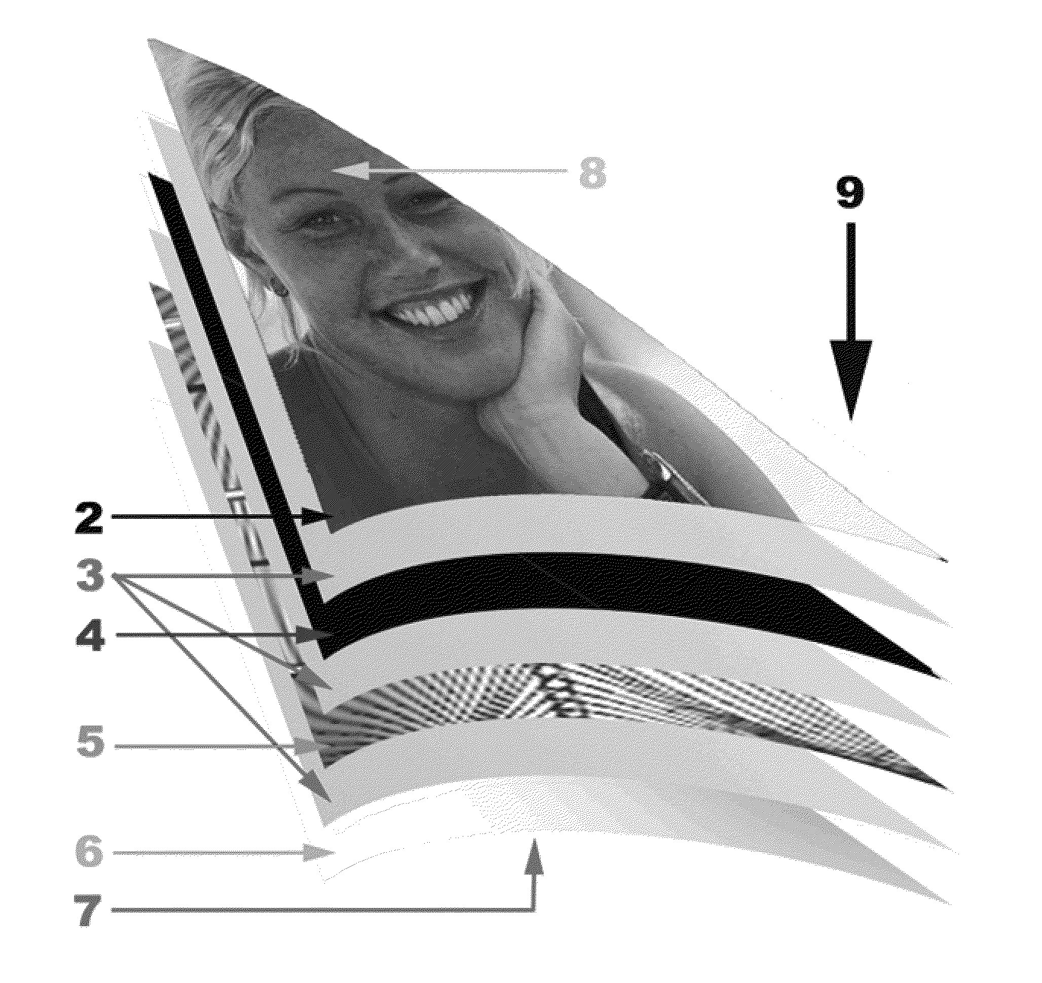
[0037]A sail 9 in accordance with one embodiment of the instant invention is manufactured with two sheets 2, 6 of clear, white or colored Mylar film from Dupont Tiejin Films with imaging / visible content 1 pre-affixed. In the exemplary embodiment, the thickness of the Mylar for both the Mylar sheets 2, 6 and an optional black Mylar sheet 4 is approximately 0.05 mil to 0.75 mil in thickness (one mil=0.001 inches or about 0.02 millimeters). Alternatively, other thicknesses of the Mylar may be used as desired for the particular sailing application. The finished sail 9 includes at least two sheets 2, 6 of clear, white or colored Mylar film sandwiching a scrim 5 of yarns placed in a load bearing fashion commonly referred to as Load Path technology. The yarns used to form the scrim 5 may consist of different materials including, but not limited to, carbon fiber yarns, Kevlar yarns, Spectra yarns, nylon yarns, Vectran yarns, and other yarns commonly used in the manufacture of high performan...

example 2

[0039]A sail 9 in accordance with another embodiment of the instant invention is manufactured in a manner similar to the sail 9 of Example 1, except that the outer sail layers 2, 6 are not pre-imaged (i.e., do not have the image pre-affixed). In this case, ink transfer sheets 20, 21 having the desired content mirror-imaged thereon are placed upon the outer layers 2, 6 prior to lamination. Heat activation and pressure during lamination cause the images from the ink transfer sheets 20, 21 to transfer from the transfer sheets 20, 21 to the exterior surfaces of the outer sail layers 2, 6 to produce the images on the sail surfaces. After lamination, the transfer sheets 20, 21 are peeled away from the sail 9 and discarded. This same process can be applied to any sail material, whether it be Dacron, Mylar, Taffeta, Canvas, Polyester, or Cotton and whether it be new, used, completed or unassembled. This process may or may not make any portion of the sail opaque, although including some form...


PUM

PropertyMeasurementUnit
Temperatureaaaaaaaaaa
Pressureaaaaaaaaaa
Adhesivityaaaaaaaaaa

Abstract

A sail includes at least two layers of durable sailcloth material, a scrim of load bearing yarns arranged in predetermined load path orientations, and at least one heat-activated adhesive layer securing the layers of material to the scrim, such that the scrim is positioned between the layers of material. An opaque layer may be included between the two outer layers of material to prevent the passage of light through the sail. Alternatively, the adhesive layer or layers may be dyed or otherwise colored to effectuate an opaque layer. The sail is preferably manufactured using a high temperature, vacuum lamination process to mitigate the quantity of voids between the layers of material and to transfer visible content from one or more image transfer mediums to the outside surface(s) of the layer(s) of material using dye sublimation to provide durable imaging. After lamination, the image transfer medium or media may be discarded.

Description

CROSS-REFERENCE TO RELATED APPLICATIONS[0001]This application is a continuation-in-part of co-pending U.S. application Ser. No. 12 / 718,669, which was filed on Mar. 5, 2010, is entitled “Sail and Method of Manufacture Thereof,” claims priority upon U.S. Provisional Application No. 60 / 209,477 for commonly disclosed subject matter, and is incorporated herein by this reference as if fully set forth herein. The present application also claims priority under 35 U.S.C. §119(e)(1) upon U.S. Provisional Application No. 61 / 284,268 filed on Dec. 16, 2009 solely to the extent of the subject matter disclosed in said provisional application, which application is incorporated herein by this reference as if fully set forth herein.BACKGROUND OF THE INVENTION[0002]1. Field of the Invention[0003]This invention relates generally to aerodynamic lift devices and, more particularly, to sailboat sails adapted to bear digitally imaged informational content.[0004]2. Description of the Background Art[0005]Com...

Claims


Application Information

Patent Timeline
IPC IPC(8): B63H9/06G09F7/00G09F21/18B32B37/02B32B37/10B32B37/06
CPCB32B37/003B32B37/1207B32B38/145B32B2305/18G09F2017/0075B32B2309/68B63H9/0657G09F21/18B32B2307/41B63H9/067
Inventor KISS, AARON
Owner KISS AARON
Why Eureka
Try Eureka