
E-Drive PWM Frequency Strategy

a technology of pulse width and frequency, applied in the direction of electric devices, motor/generator/converter stoppers, process and machine control, etc., can solve the problems of generating noise audible to the vehicle driver, his passengers, distracting and irritating noise, etc., to reduce pwm noise reduce pwm noise

Active Publication Date: 2011-07-14
FORD GLOBAL TECH LLC
View PDF22 Cites 31 Cited by
  • Summary
  • Abstract
  • Description
  • Claims
  • Application Information

AI Technical Summary

Benefits of technology

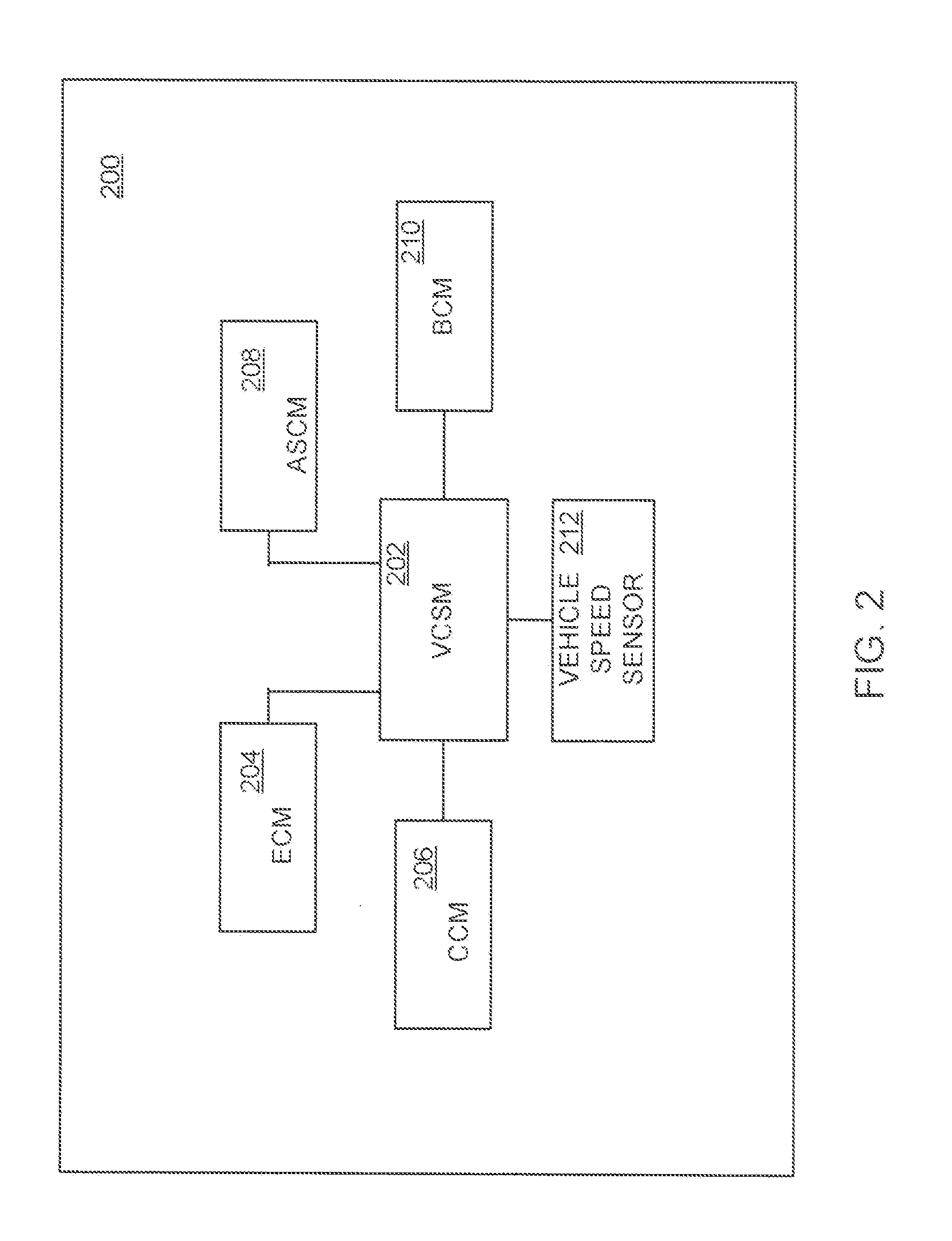
The patent describes a pulse width modulation (PWM) Frequency Adaptation Mechanism (PFAM) for an electric drive system of a vehicle. The PFAM receives vehicle state input and user preference input and designs one or more PWM parameters accordingly. The PWM parameters can include a PWM switching frequency and / or strategy, such as continuous, discontinuous, or random PWM. The PFAM can be in the form of a software module installed at a microprocessor or other computing device of the vehicle. The technical effect of the invention is to reduce PWM noise in the vehicle by selecting a PWM parameter based on the received input, such as a default lower PWM switching frequency when noise sources are present. The PFAM can be in the form of a module that interacts with other control modules of the vehicle to provide the PWM parameter(s) for the electric drive system.

Problems solved by technology

Unfortunately, in many cases, switching the various electronic devices on and off at a particular frequency can generate noise audible to the vehicle driver, as well as his passengers.
The noise can be distracting and irritating, and is often the subject of consumer complaints.
However, this solution has its disadvantages.
While the higher switching frequency no longer generates noise heard by the operator, it induces power losses in the system that can reduce fuel economy, a long-standing priority for hybrid vehicles, and increase power circuit costs.

Method used


Image

  • E-Drive PWM Frequency Strategy
  • E-Drive PWM Frequency Strategy
  • E-Drive PWM Frequency Strategy

Examples


Embodiment Construction

[0018]Example embodiments of the invention are presented herein; however, the invention may be embodied in a variety of alternative forms, as will be apparent to those skilled in the art. To facilitate understanding of the invention, and provide a basis for the claims, various figures are included in the description. The figures are not drawn to scale and related elements may be omitted so as to emphasize the novel features of the invention. Structural and functional details depicted in the figures are provided for the purpose of teaching the practice of the invention to those skilled in the art and are not to be interpreted as limitations. For example, control modules for various systems can be variously arranged and / or combined, and are not to be considered limited to the example configurations presented herein.

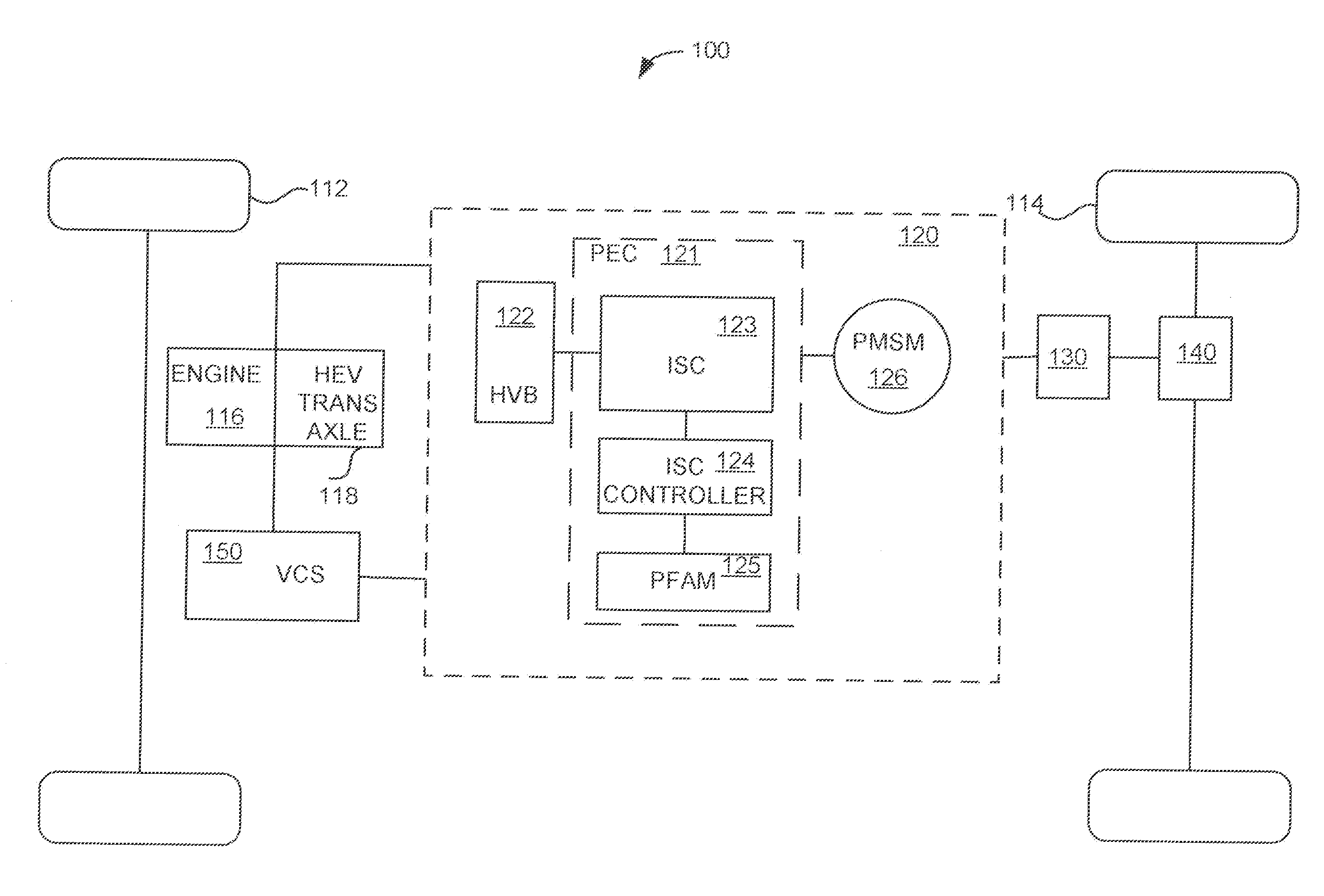
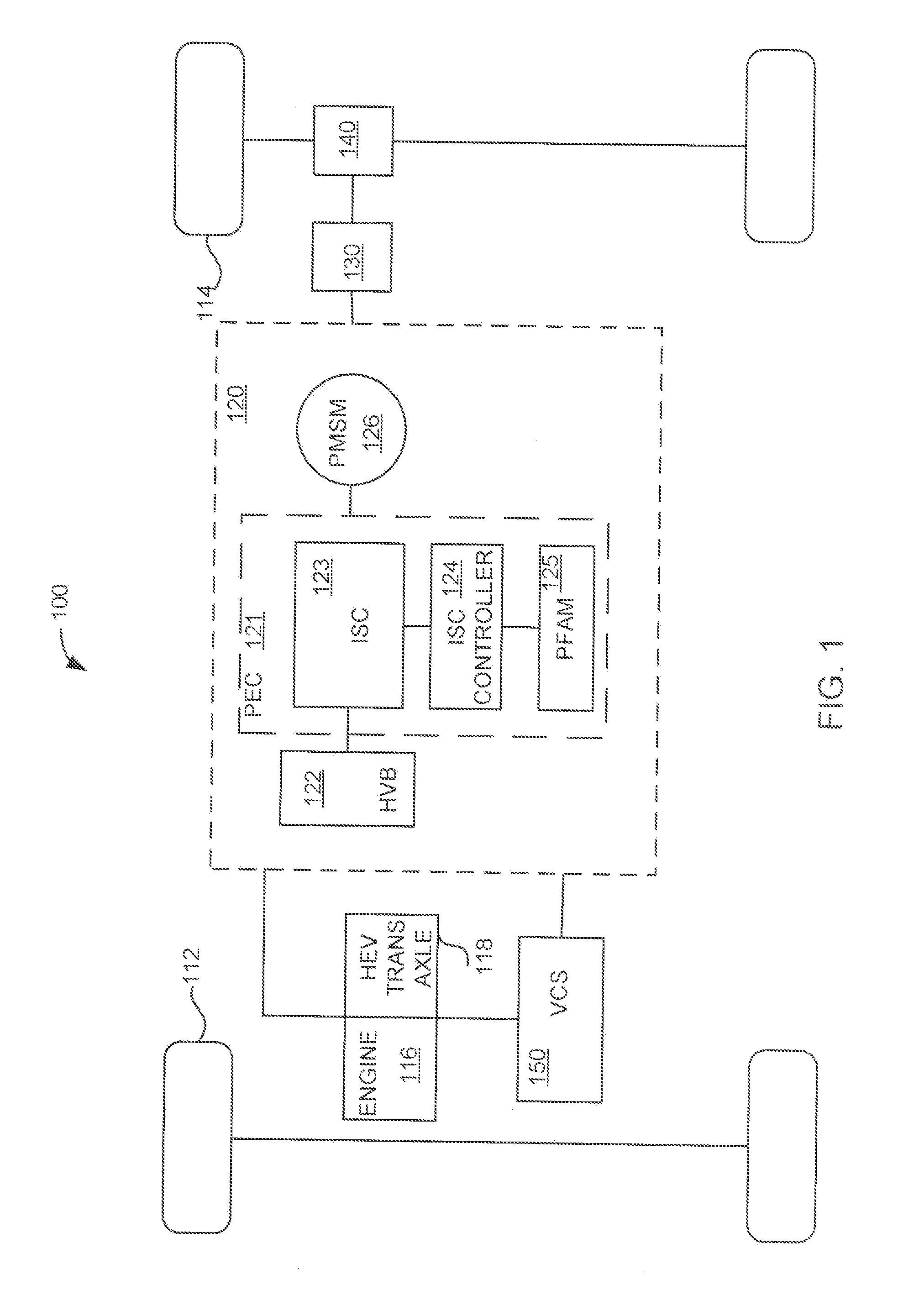
[0019]FIG. 1 illustrates a schematic of an example vehicle 100. The vehicle 100 may be of any suitable type, such as an electric or hybrid electric vehicle. In at least one...


PUM


Abstract

A pulse width modulation (PWM) Frequency Adaptation Mechanism (PFAM) is configured to receive vehicle state input, and in response to the vehicle state input, provide a PWM parameter for PWM switching of electronics in a power conversion circuit of an electric drive system (EDS) for a hybrid electric vehicle. In one example, a PWM parameter that reduces the audible noise generated by PWM switching can be designated by the PFAM. A PFAM can be configured to receive user input regarding user preference for a default mode or a noise reduction mode. Vehicle state input can include input related to vehicle motion, climate control system state, engine state, EDS state, vehicle body state and audio system state. By way of example, a PWM noise reduction parameter can comprise a high PWM switching frequency, or a random frequency hopping about a low PWM switching frequency.

Description

BACKGROUND OF INVENTION[0001]1. Field of Invention[0002]The present invention relates to electric drive systems. In particular, the invention pertains to pulse width modulation (PWM) strategies employed at an electric drive system.[0003]2. Background Art[0004]Electric machines, in particular electric or hybrid electric vehicles, may employ electrical energy for propulsion via an electric drive system. An electric drive system can encompass a number of components, typically including at least a power circuit and a motor. In this arrangement, the power circuit can controllably transfer power from a power source to the motor to drive a load. Power circuits for electric drive systems designed for electric or hybrid electric vehicles often include inverters for providing three-phase voltage waves from a dc voltage source. Typically an inverter is composed of a plurality of electronic switches that are controllably turned off and on in various combinations to provide desired inverter outp...

Claims


Application Information

Patent Timeline
Patent Type & Authority Applications(United States)
IPC IPC(8): G06F19/00H02P6/10B60L50/15B60L50/16
CPCB60L15/02B60L15/20Y02T10/7275H02P6/001H02P6/10B60L2270/14B60L1/003B60L3/003B60L2210/40B60L2220/12B60L2240/12B60L2240/26B60L2240/34B60L2240/36B60L2240/421B60L2240/423B60L2250/12B60L2250/16B60L2270/142H02P6/34B60L50/61B60L50/16Y02T10/62Y02T10/64Y02T10/72Y02T10/7072Y02T10/70
Inventor SANKARAN, VENKATESWAXIANG, JOE YOUQING
Owner FORD GLOBAL TECH LLC
Learn More