
Digital broadcast receiver

a digital and receiver technology, applied in the field of digital broadcast receivers, can solve the problem that external inputs or the like cannot be viewed during the entire waiting time, and achieve the effect of reducing the waiting tim

Inactive Publication Date: 2011-07-14
SHARP KK
View PDF5 Cites 5 Cited by
  • Summary
  • Abstract
  • Description
  • Claims
  • Application Information

AI Technical Summary

Benefits of technology

[0010]The digital broadcast receiver according to the present invention is characterized in that, when an optical disc is inserted into the receiver, a display screen of a double-screen configuration including a first display area and a second display area is displayed. Here, the first display area displays digital broadcast or external input contents, and the second display area displays a message indicating that the optical disc is being prepared. In this manner, the message can be displayed simultaneously with displayed contents without interrupting viewing of the displayed contents.

Problems solved by technology

However, if the message alone is displayed, broadcast contents, external input or the like cannot be viewed during the entire waiting time.

Method used


Image

  • Digital broadcast receiver
  • Digital broadcast receiver
  • Digital broadcast receiver

Examples


first embodiment

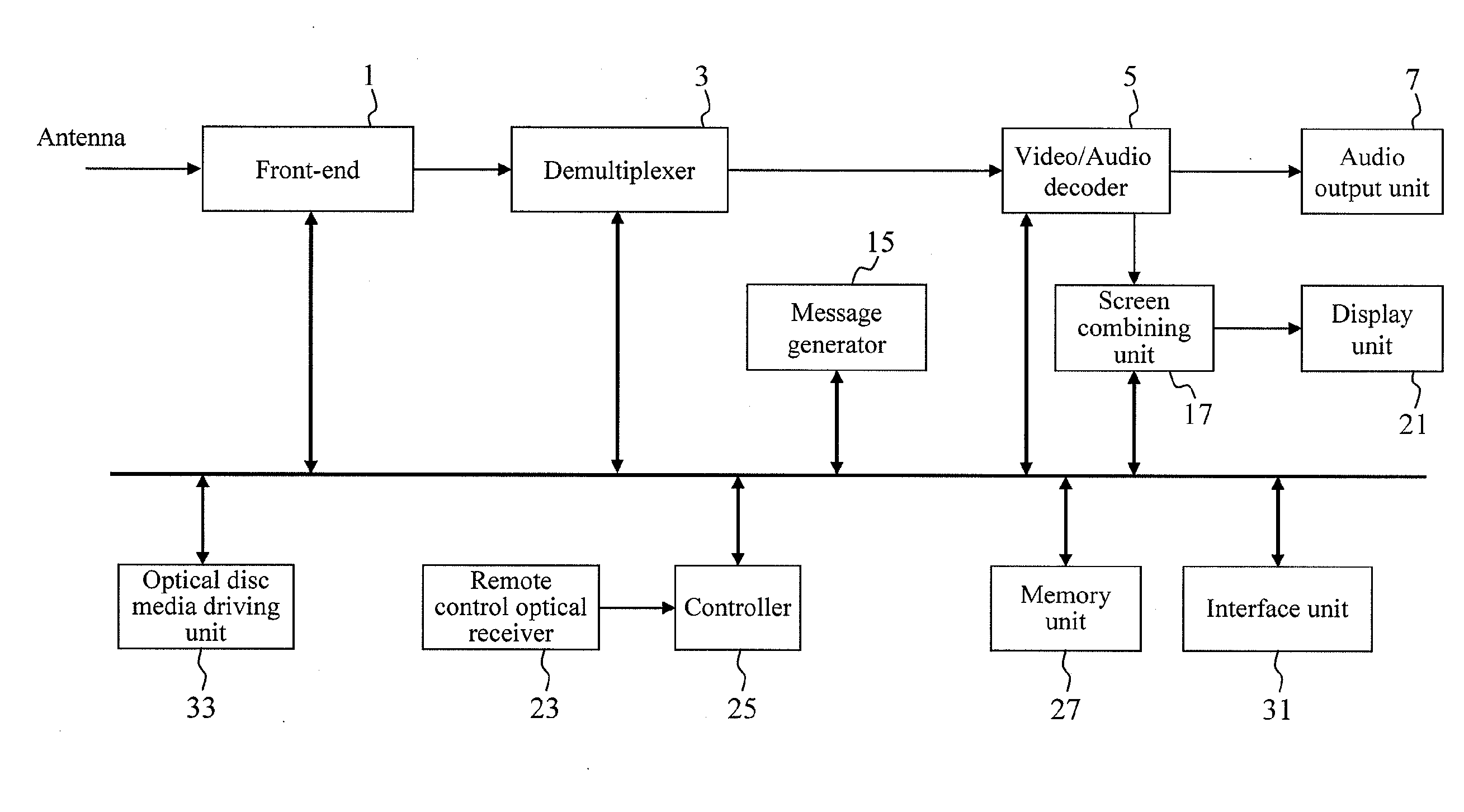
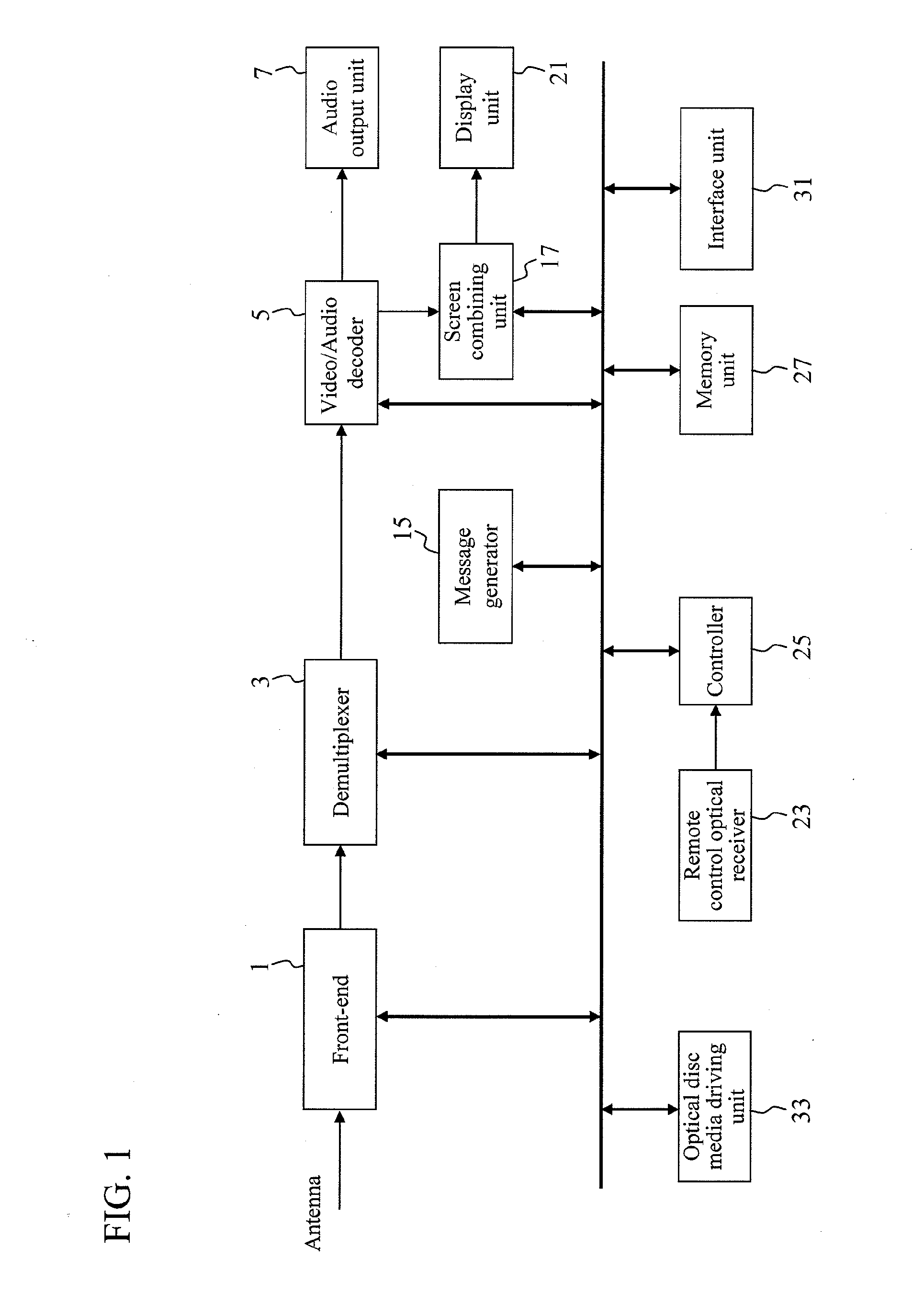
[0061]Hereinafter, a digital broadcast receiver according to an embodiment of the present invention will be described with reference to the drawings. FIG. 1 is a block diagram showing an example of a configuration of the digital broadcast receiver of the present embodiment. The digital broadcast receiver shown in FIG. 1 is a digital television receiver including a recording and playing back function, which is a so-called recorder built-in television apparatus, but the present invention is not limited to such a recorder built-in apparatus.

[0062]As illustrated in FIG. 1, the digital broadcast receiver according to the embodiment of the present invention includes: a front-end 1 configured to perform processing such as receiving a digital broadcast signal received by an antenna and thereby selecting a station; a demultiplexer 3; a video / audio decoder 5 configured to decode output from the demultiplexer 3; a screen combining unit 17 configured to generate a signal for combining a decoded...

second embodiment

[0077]In the first embodiment, the processing to be performed when an optical disc is inserted has been described. Meanwhile, in a second embodiment, a description is given of a case where contents are recorded in a storage device such as a built-in hard disk, a hard disk connected via USB or Ethernet (registered trademark) or a flash memory connected via USB. The second embodiment can be carried out simultaneously with the first embodiment.

[0078]FIG. 4 is a block diagram showing another example of a configuration of a digital broadcast receiver of the present embodiment. The digital broadcast receiver shown in FIG. 4 is a digital television receiver including a recording and playing back function, which is a so-called recorder built-in television apparatus, but the present invention is not limited to such a recorder built-in apparatus.

[0079]As illustrated in FIG. 4, like the digital broadcast receiver according to the first embodiment illustrated in FIG. 1, the digital broadcast re...

third embodiment

[0090]In addition to the configuration and operation according to the first and second embodiments, when a read-only optical disc is inserted, after completion of the preparation of the optical disc, the playback screen of the contents is displayed in a reduced size in the first display area, and the viewing screen of digital broadcast or the screen of external input contents or the like is displayed in the second display area as a thumbnail video. FIG. 7 is a flowchart for describing a flow of processing in this case. The processing will be described by also referring to the display screen examples shown in FIG. 8A to FIG. 8C.

[0091]In step S301, suppose that the display unit 21 displays the viewing screen of digital broadcast with the single screen configuration as shown in FIG. 8A, for example. Then, in step S302, a read-only optical disc is inserted into the optical disc media driving unit 33, and reading of disc information or the like is performed. In step S303, the controller ...


PUM

PropertyMeasurementUnit
areaaaaaaaaaaa
sizeaaaaaaaaaa
waiting timeaaaaaaaaaa

Abstract

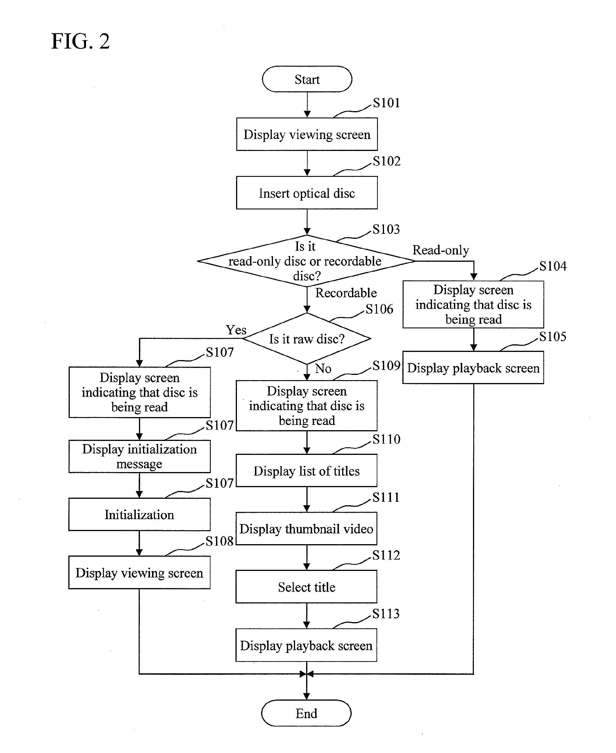
Provided is a digital broadcast receiver capable of displaying a message, a list of titles of contents or the like together with a viewing screen without interrupting viewing of contents. The digital broadcast receiver includes a controller 25 configured to determine whether an optical disc inserted into the receiver is a read-only optical disc or a recordable optical disc and also to control a display screen. Upon insertion of an optical disc, the controller 25 causes a display screen including a first display area and a second display area to be displayed, the first display area displaying digital broadcast or external input contents, the second display area displaying a message indicating that the optical disc is being prepared. In a case where the optical disc is a read-only optical disc, the controller 25 causes only a playback screen of contents recorded in the optical disc to be displayed upon completion of the preparation of the optical disc. In a case where the optical disc is a recordable disc, the controller 25 causes a list of titles of contents recorded in the optical disc to be further displayed in the second display area, and deletes the message in the second display area upon completion of the preparation of the optical disc.

Description

TECHNICAL FIELD[0001]The present invention relates to a digital broadcast receiver.BACKGROUND ART[0002]In recent years, among digital broadcast receivers for receiving and displaying digital broadcast, there have been introduced receivers having functions to record contents in a recording medium or an external storage device and also to play back contents recorded in a recording medium or an external recording device. Here, examples of the recording medium include a DVD-R, DVD-RW, Blu-ray Disc, hard disk (HDD), memory card and the like.[0003]When an optical disc such as a DVD-R, DVD-RW or Blu-ray Disc is used, reading of disc information or the like is required. Accordingly, a predetermined waiting time is needed before the contents recorded in the optical disc are ready for playback after the optical disc is inserted into the digital broadcast receiver.[0004]Here, a message informing the user that the optical disc is being prepared is preferably displayed. However, if the message a...

Claims


Application Information

Patent Timeline
Patent Type & Authority Applications(United States)
IPC IPC(8): G11B27/36H04N5/44H04N5/93H04N7/173
CPCG11B27/105G11B27/34G11B2220/2537H04N5/85H04N9/8042H04N21/4882H04N21/4312H04N21/4314H04N21/4325H04N21/440263H04N21/482H04N21/42646
Inventor HIROTA, TORU
Owner SHARP KK
Learn More