Image quality evaluation device, terminal device, image quality evaluation system, image quality evaluation method and computer-readable recording medium for storing programs

a technology of image quality and evaluation device, which is applied in the direction of static indicating device, television system, instruments, etc., can solve problems such as difficult reflection, and achieve the effect of preventing blurring of images

Inactive Publication Date: 2011-07-14
NEC CORP
View PDF5 Cites 43 Cited by
  • Summary
  • Abstract
  • Description
  • Claims
  • Application Information

AI Technical Summary

Benefits of technology

[0004]In some images displayed by a terminal device such as a mobile phone, high-frequency components are emphasized by signal processing such as edge emphasis to prevent blurring of the image. In some of this kind of images, jaggies (zigzags created at edges), an ill effect caused by emphasizing high-frequency components, and noise and so on exist. In the aforementioned video resolution evaluation device, it is difficult to reflect jaggies and noise in the evaluation results even if the overall image quality falls as a result of these.

Problems solved by technology

In some of this kind of images, jaggies (zigzags created at edges), an ill effect caused by emphasizing high-frequency components, and noise and so on exist.
In the aforementioned video resolution evaluation device, it is difficult to reflect jaggies and noise in the evaluation results even if the overall image quality falls as a result of these.

Method used


Image

  • Image quality evaluation device, terminal device, image quality evaluation system, image quality evaluation method and computer-readable recording medium for storing programs
  • Image quality evaluation device, terminal device, image quality evaluation system, image quality evaluation method and computer-readable recording medium for storing programs
  • Image quality evaluation device, terminal device, image quality evaluation system, image quality evaluation method and computer-readable recording medium for storing programs

Examples


first embodiment

[0053]First, a first exemplary embodiment of the present invention is described. In this embodiment, the explanation is for an image quality evaluation system for evaluating the quality of an image shot by a camera-equipped mobile phone.

[0054]FIG. 1 shows the entire composition of an image quality evaluation system 100 according to the present exemplary embodiment. As shown in FIG. 1, the image quality evaluation system 100 is equipped with a mobile phone 1, a display device 2 and a personal computer (hereafter, abbreviated as “computer”) 3.

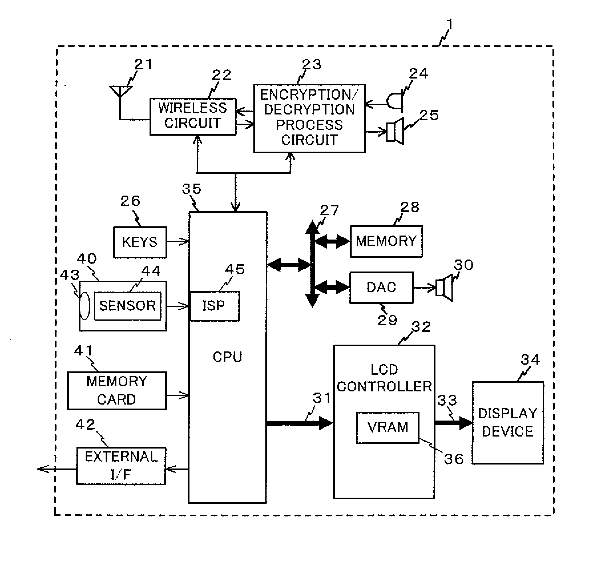
[0055]The mobile phone 1 is a camera-equipped mobile phone. FIG. 2 shows the internal composition of the mobile phone 1. As shown in FIG. 2, the mobile phone 1 has a communications antenna 21, a wireless circuit 22, an encryption / decryption processing circuit 23, a mike 24, a receiver 25, keys 26, a CPU (Central Processing Unit) bus 27, a memory 28, a DAC (Digital Analog Converter) 29, a speaker 30, a video I / F 31, an LCD (Liquid Crystal Display)...

second exemplary embodiment

[0114]Next, the second exemplary embodiment of the present invention is described. The composition and action of the image quality evaluation system 100 according to the present exemplary embodiment is the same as that shown in FIGS. 1 and 9.

[0115]However, in the present exemplary embodiment, the composition of the sensor 44 of the mobile phone 1 differs. In the above-described first exemplary embodiment, a monochrome type was used for the sensor 44 of the mobile phone 1, but in the present exemplary embodiment, the sensor 44 has a color sensor provided with RGB color filters in each pixel.

[0116]FIG. 10 shows the RGB pixel arrangement in the sensor 44. As shown in FIG. 10, G and R are alternately positioned on the first line of this arrangement. In addition, B and G are alternately positioned on the second line. Furthermore, G and R are alternately positioned on the third line. This kind of pixel arrangement is generally called a Bayer arrangement because G is positioned in a stagge...

embodiment 3

[0131]Next, a third exemplary embodiment of the present invention is described.

[0132]In the above-described first exemplary embodiment, the case was explained wherein image quality is evaluated by paying attention to jaggies caused by the digital zoom. In addition, in the above-described second exemplary embodiment the case of evaluating jaggies caused by pixel summation was explained. In contrast, in the present exemplary embodiment, the case will be explained for evaluating distortion (block noise or mosquito noise) generated by digital compression.

[0133]With MPEG, an image data compression process is accomplished in block units called macro blocks composed of 16 pixels horizontally and 16 pixels vertically. Accordingly, in this image data, distortion occurs readily in macro block units. Distortion caused by the MPEG compression process can also be evaluated by frequency spectrum analysis by the computer 3.

[0134]FIG. 15 shows the entire composition of an image quality evaluation s...


PUM


Abstract

The present invention evaluates the quality of an image shot by a terminal device in a state closer to that seen with the eye. A computer evaluates the quality of an image obtained by shooting a photographic subject including a periodic pattern that fluctuates periodically in one direction. A Fourier transform unit accomplishes a two-dimensional Fourier transform on the image to obtain two-dimensional spatial frequency spectrum components. An analysis unit analyzes the resolution of the image on the basis of spectrum components of spatial frequencies included in the periodic pattern, among the two-dimensional spatial frequency spectrum components obtained by the Fourier transform unit, and analyzes the deterioration of the image on the basis of spectrum components other than these.

Description

INCORPORATION BY REFERENCE[0001]This application is based on the Japanese Patent Application No. 2010-004256 filed on Jan. 12, 2010 and including specification, claims, drawings and summary. The disclosure of the above Japanese Patent Application is incorporated herein by reference in its entirety.TECHNICAL FIELD[0002]The present invention relates to an image quality evaluation device for evaluating the quality of an image taken by a terminal device such as a digital camera or a mobile phone, a terminal device equipped with this image quality evaluation device, an image equality evaluation system equipped with the image quality evaluation device or the terminal device, an image quality evaluation method for evaluating the quality of an image taken by a terminal device such as a digital camera or a mobile phone, and a computer-readable recording medium for storing programs to be executed by a computer.BACKGROUND ART[0003]A video resolution evaluation device for evaluating the video r...

Claims


Application Information

Patent Timeline
Patent Type & Authority Applications(United States)
IPC IPC(8): G06K9/46G06K9/00H04N5/225G09G5/00
CPCG06K9/036H04N5/232G06K9/4652H04N17/002G06K9/46H04N5/23229G06V10/993H04N23/60H04N23/80H04N25/134
Inventor MASUDA, KOZO
Owner NEC CORP
Why Eureka
Try Eureka