
Induction motor control systems and methods

Active Publication Date: 2011-07-07
GM GLOBAL TECH OPERATIONS LLC
View PDF6 Cites 21 Cited by
  • Summary
  • Abstract
  • Description
  • Claims
  • Application Information

AI Technical Summary

Benefits of technology

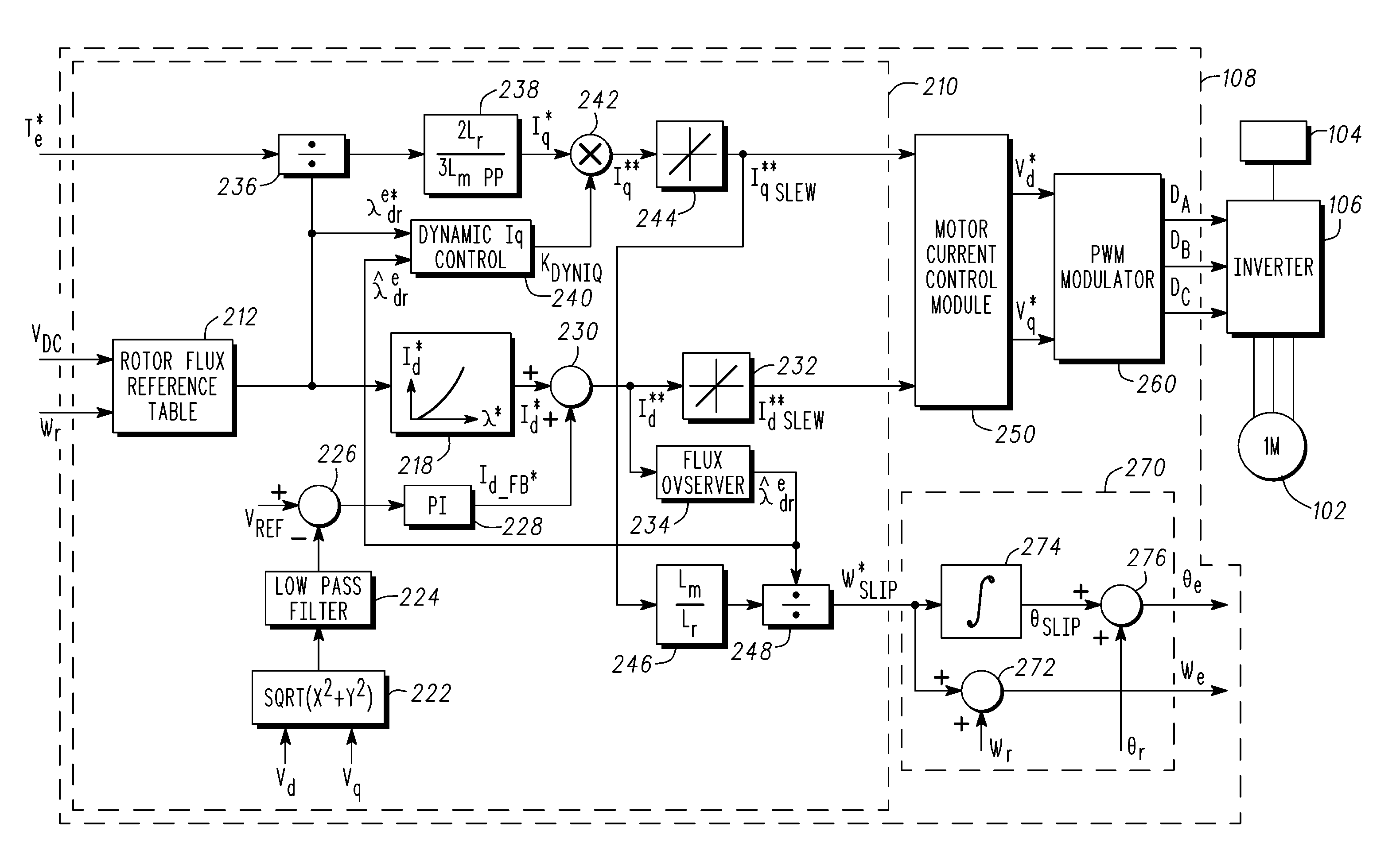
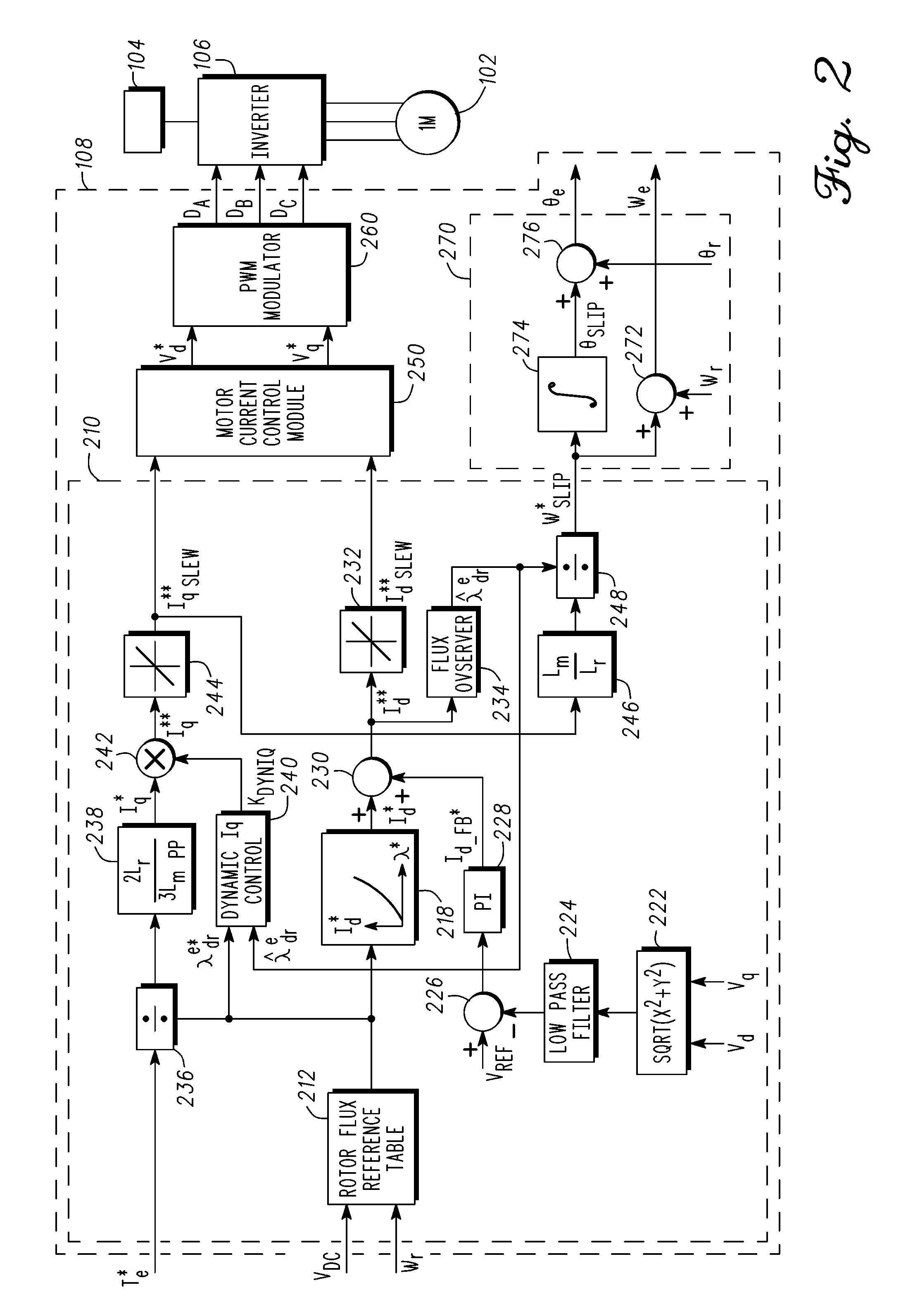
[0006]In accordance with an exemplary embodiment, a control system is provided for an inverter assembly associated with an induction motor. The system includes a current determination module configured to generate q- and d-axis current commands based on a torque command. The current determination module is further configured to generate the q-axis current command based on an observed flux linkage and a flux linkage command. The system further includes

Problems solved by technology

One of the changes involves the power usage and complexity of the various electrical systems within automobiles, particularly alternative fuel vehicles, such as hybrid, electric, and fuel cell vehicles.
Some conventional systems may have a delay between the torque command and the actual torque response.
Particularly, during transient time periods, the true d-axis flux linkage changes slower than the d-axis current on which it is built as a result of the inherent rotor time constant of the motor, which may cause the torque delays.

Method used


Image

  • Induction motor control systems and methods
  • Induction motor control systems and methods
  • Induction motor control systems and methods

Examples


Embodiment Construction

[0013]The following detailed description is merely exemplary in nature and is not intended to limit the invention or the application and uses of the invention. Furthermore, there is no intention to be bound by any expressed or implied theory presented in the preceding technical field, background, brief summary or the following detailed description.

[0014]Broadly, exemplary embodiments disclosed herein relate to a control system for an inverter assembly of an induction motor. The control system uses a dynamic Iq control to reduce torque delay, particularly during transient time periods. In one exemplary embodiment, the control system modifies the q-axis current command with a scaling factor selected based on observed and command flux linkages.

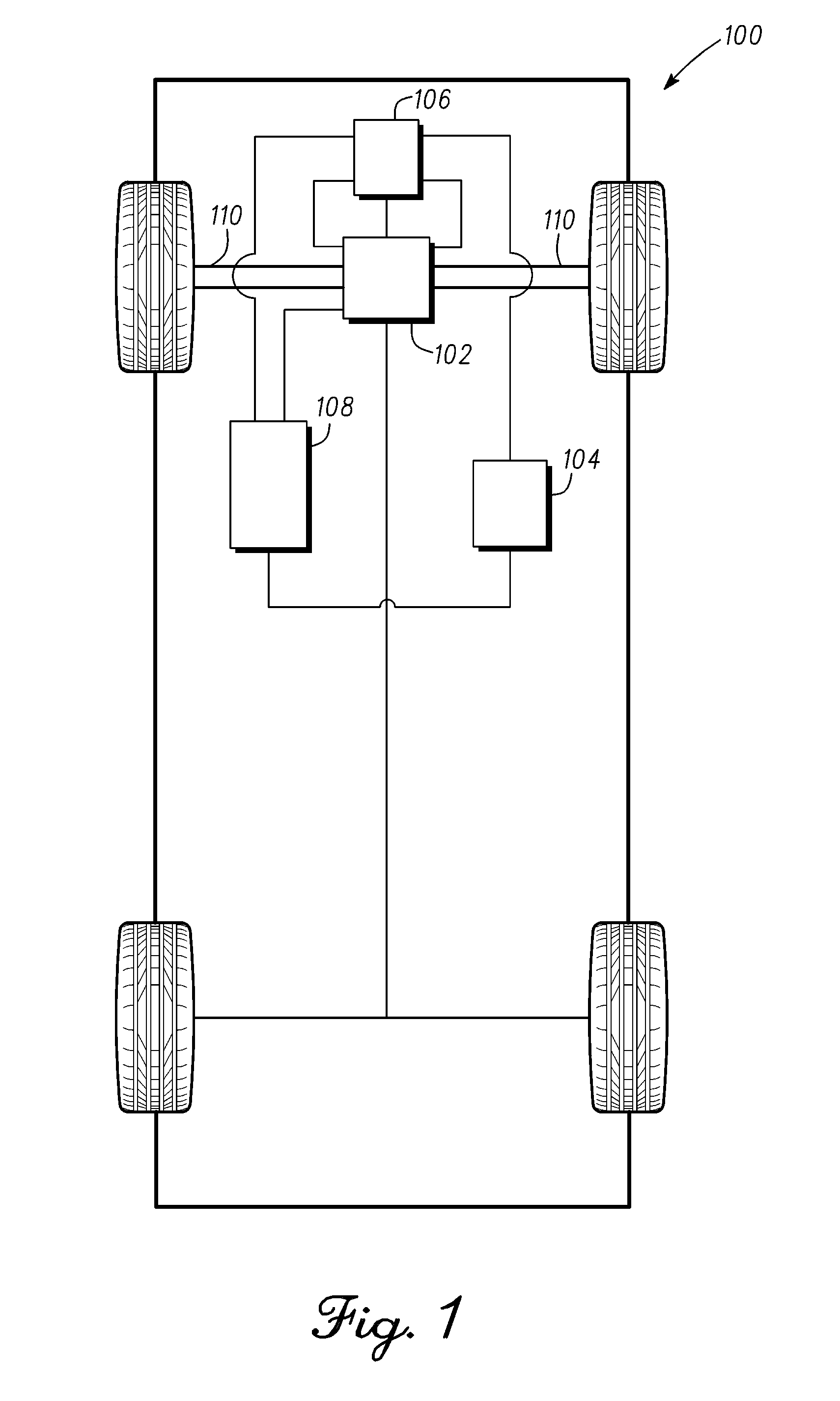
[0015]FIG. 1 illustrates a vehicle, or automobile 100, in accordance with an exemplary embodiment, which includes an induction motor 102, an energy source 104, an inverter assembly 106, an electronic control system 108, and a drive shaft 110. In ...


PUM


Abstract

A control system is provided for an inverter assembly associated with an induction motor. The system includes a current determination module configured to generate q- and d-axis current commands based on a torque command. The current determination module is further configured to generate the q-axis current command based on an observed flux linkage and a flux linkage command. The system further includes a motor current control module coupled to the current determination module and configured to generate q- and d-axis voltage commands based on the q- and d-axis current commands generated by the current determination module and a PWM modulator coupled to the motor current control module configured to generate duty cycle signals for operating the inverter assembly based on the q- and d-axis voltage commands generated by the motor current control module.

Description

TECHNICAL FIELD[0001]The present invention generally relates to induction motors, and more particularly relates to systems and methods for controlling induction motors found in hybrid vehicles and other applications.BACKGROUND[0002]In recent years, advances in technology, as well as evolving tastes in style, have led to substantial changes in the design of automobiles. One of the changes involves the power usage and complexity of the various electrical systems within automobiles, particularly alternative fuel vehicles, such as hybrid, electric, and fuel cell vehicles. Many of these vehicles use electric motors, such as induction motors, to convert electrical power to mechanical power to provide traction power to the vehicle.[0003]Motor vehicle applications typically employ a three-phase AC induction motor. In an induction motor, a stator includes a number of wound poles carrying supply current to induce a magnetic field that penetrates the rotor. Typically, an electronic control sys...

Claims


Application Information

Patent Timeline
IPC IPC(8): H02P21/08
CPCH02P21/06H02P2207/01H02P21/141Y02T10/72
Inventor DAI, MINBAE, BON HODUNBAR, LEAH
Owner GM GLOBAL TECH OPERATIONS LLC
Learn More