
Uplink power alignment estimation in a communication system

a communication system and power alignment technology, applied in power management, wireless communication, wireless commuication services, etc., can solve the problems of power misalignment between the ue and the enb, severe limited rf channel conditions, and additional interference in the system

Active Publication Date: 2011-06-30
GOOGLE TECH HLDG LLC
View PDF6 Cites 34 Cited by
  • Summary
  • Abstract
  • Description
  • Claims
  • Application Information

AI Technical Summary

Problems solved by technology

As a result, interference from other sectors / cells may occur in this system, and therefore it is important to control user equipment (UE) transmit power levels.
However, there may be instances where a UE will not receive these TPC commands from the eNB.
This is especially true for UEs at the edge of a cell or at bad coverage locations resulting in severely limited RF channel conditions, such as during deep-fade scenarios.
Losing TPC bits in a channel due to RF conditions can lead to a power misalignment between the UE and the eNB.
Without proper agreement between a UE and eNB, one or the other could end up transmitting at full power resulting in additional interference in the system.
However, switching back and forth between using absolute or accumulated TPC bits requires layer 2 messages and will take additional time.
Even so, such instructions may not reach to the UE due to the same poor channel conditions that made the UE lose the TPC bits in the first place.
Again this requires additional messaging and time, and such messages may not reach to the eNB due to the same poor channel conditions.
However, this solution then assume subsequent TPC bit generation corresponding to a 0 dB adjustment, which may be a completely incorrect assumption.

Method used


Image

  • Uplink power alignment estimation in a communication system
  • Uplink power alignment estimation in a communication system
  • Uplink power alignment estimation in a communication system

Examples


Embodiment Construction

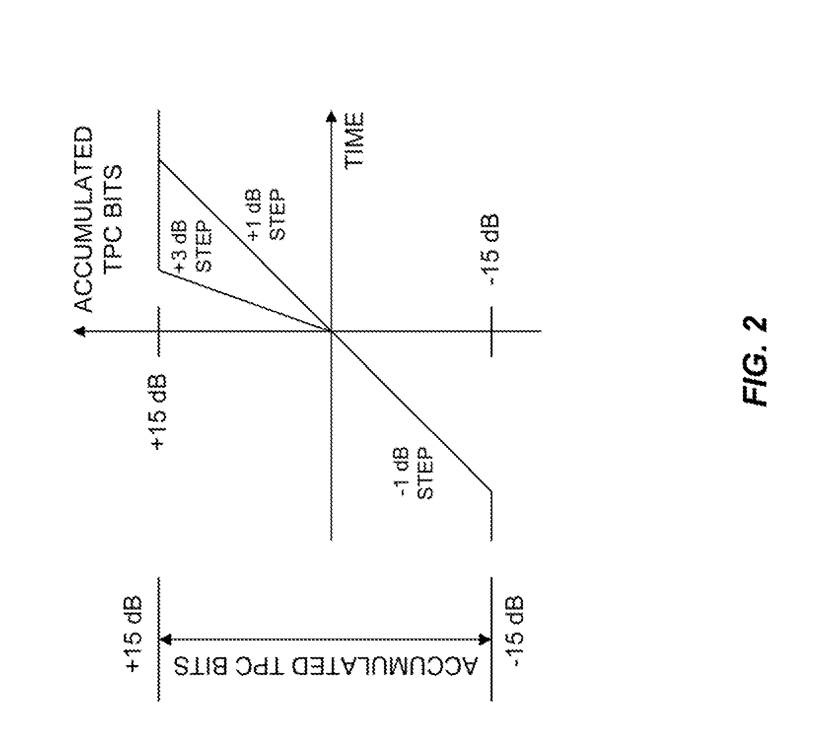
[0016]The present invention provides an uplink power alignment estimation technique to address the situation where TPC bits are lost, without the need to utilize additional messaging. In particular, in order to maintain parity between an accumulated power control delta of the eNB and UE during periods of lost communication, the eNB continues transmitting power control updates even when the accumulated value reaches a threshold (e.g. + / −15 dB). When acknowledged communication is restored, the eNB makes subsequent power control updates assuming the UE is at the accumulated value threshold—if reached.

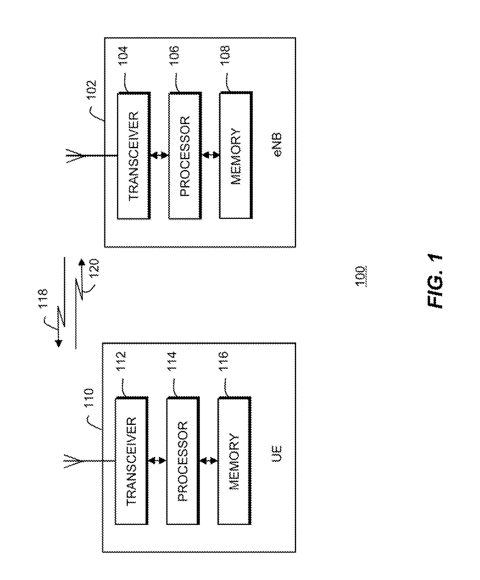
[0017]Referring to FIG. 1, a block diagram is shown of a wireless communication system 100 in accordance with the present invention. Communication system 100 includes an evolved NodeB (eNB) 102 that provides wireless communication services to a user equipment (UE) 110 residing in a coverage area, such as a cell or a sector, of the eNB via a respective air interface, such as an evolved UMTS...


PUM


Abstract

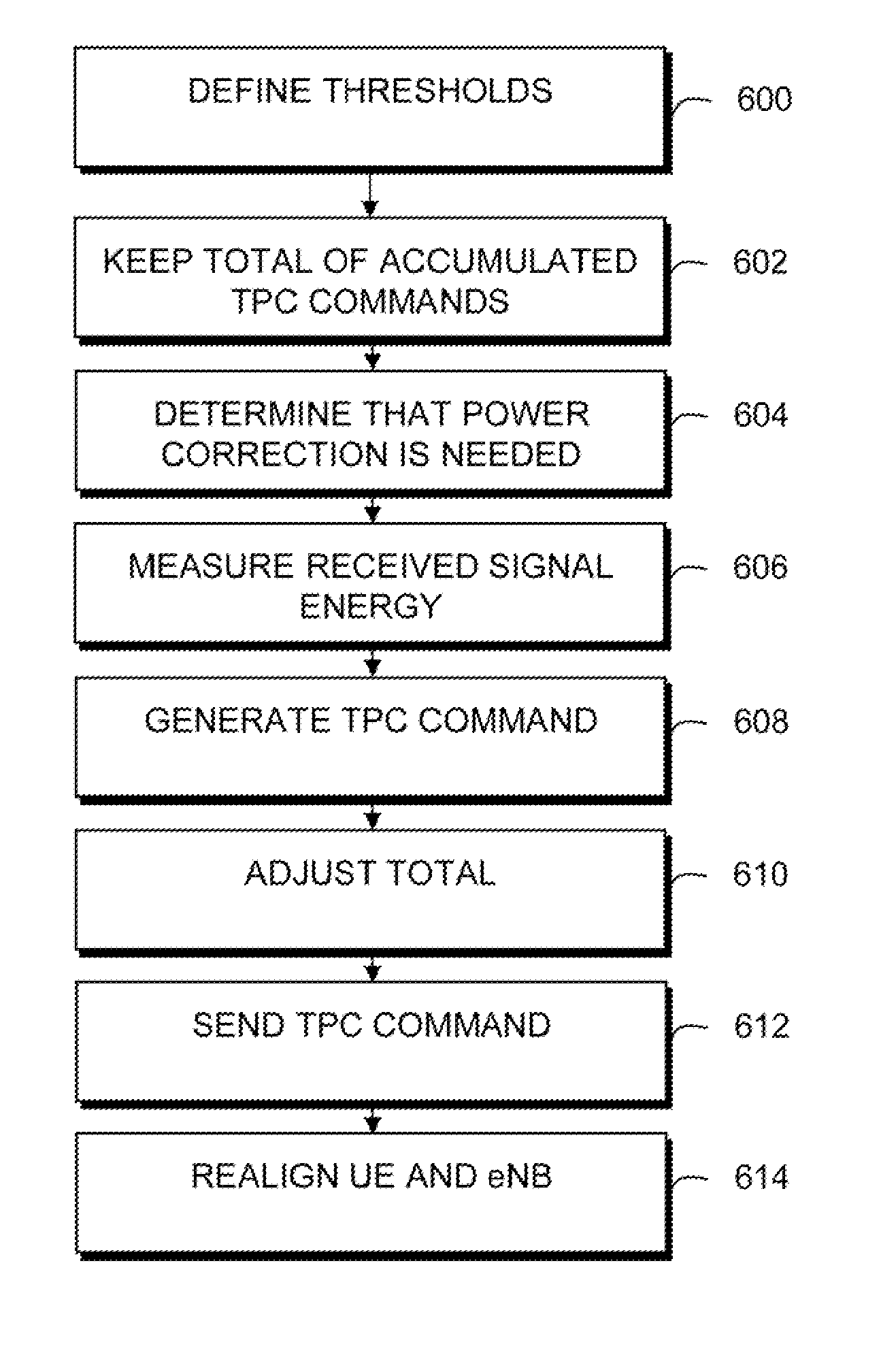
A method and apparatus for uplink power alignment estimation in a communication system includes a step 600 of defining an upper threshold and a lower threshold for a transmit power correction (TPC) level. A next step 602 includes keeping a total of accumulated TPC commands. A next step 604 includes determining that a power correction is needed. A next step 608 includes generating a TPC command to be sent to a user equipment per the needed power correction. A next step 610 includes adjusting the total according to one of the following conditions: if the total is between the upper and lower thresholds then the total is changed per the needed power correction, if the total is at either of the thresholds and the needed power correction would not exceed either of the thresholds then the total is changed per the needed power correction, and if the total is at either of the thresholds and the needed power correction would exceed either of the thresholds then total is kept the same.

Description

FIELD OF THE INVENTION[0001]The present invention relates generally to Frequency Division Multiple Access (FDMA) and Orthogonal Frequency Division Multiple Access (OFDMA) communication systems, and, in particular, to uplink power alignment estimation in FDMA and OFDMA communication systems.BACKGROUND OF THE INVENTION[0002]Single Carrier and Multi-Carrier Frequency Division Multiple Access (FDMA) communication systems, such as Interleaved FDMA, OFDMA, and Discrete Fourier Transform Spread OFDMA communication systems, have been proposed for use in Fourth Generation (4G) communication systems, such as Long Term Evolution (LTE) communication system, for transmission of data over an air interface. In Single Carrier and Multi-Carrier FDMA communication systems, a frequency bandwidth is split into multiple contiguous frequency sub-bands, or sub-carriers, that are transmitted simultaneously. A user may then be assigned one or more of the frequency sub-bands for an exchange of user informati...

Claims


Application Information

Patent Timeline
IPC IPC(8): H04B7/005H04W72/04H04W52/00
CPCH04W52/146H04W52/545H04W52/367H04W52/221
Inventor CHEN, JIANGNAN JASONSHIHAB, JAMIL M.
Owner GOOGLE TECH HLDG LLC
Learn More