
Reagent Cabinet System

a technology of reagent cabinet and reagent, which is applied in the direction of burettes/pipettes, material analysis, packaging goods types, etc., can solve the problems of system prone to operator errors, identity loss, improper testing,

Active Publication Date: 2011-06-30
BECTON DICKINSON & CO
View PDF3 Cites 106 Cited by
  • Summary
  • Abstract
  • Description
  • Claims
  • Application Information

AI Technical Summary

Benefits of technology

The present invention provides a reagent cabinet for an automated processing apparatus. The reagent cabinet has a housing and a drawer slidably mounted in the housing. The drawer has a lower deck for receiving a fluid reservoir and an upper deck for receiving a fluid supply container. A supply connection hose connects the fluid supply container to the fluid reservoir, and a reservoir connection hose connects the fluid reservoir to a downstream location outside the cabinet. A pump is mounted on the drawer and can convey fluid through either the supply connection hose or the reservoir connection hose. The technical effect of this invention is to provide a convenient and efficient way to supply fluid to an automated processing apparatus.

Problems solved by technology

Such systems can be prone to operator error in many forms, such as improper testing (e.g., using an improper reagent or mis-reading the results), sample loss (e.g., spilling a sample), and identity loss (e.g., losing the patient name or associating the sample with the incorrect patient).
While automated and semi-automated methods may help reduce labor costs and operator error, many automated systems are cumbersome to use.
For example, many “automated” systems are actually only semi-automated, and may require labor-intensive pre-processing steps to transfer the input samples into a format, such as a particular sample container, that the machine can accept.
It has also been found that existing semi-automated systems may lack safety controls, require frequent stopping for service, operate inefficiently or slowly, or have other problems or shortcomings.

Method used


Image

  • Reagent Cabinet System
  • Reagent Cabinet System
  • Reagent Cabinet System

Examples


Embodiment Construction

[0018]The present disclosure provides various exemplary embodiments of automated or semi-automated sample processing systems, methods for automated, high-throughput sample processing, control systems for coordinating and controlling the operations of a high-throughput specimen processing systems, and various devices that may be used in the foregoing sample processing systems or in other processes, devices or systems. Preferred embodiments of the invention may provide faster, more reliable, and cheaper methods and machines for high-throughput patient sample processing, but other benefits may be realized instead of or in addition to these.

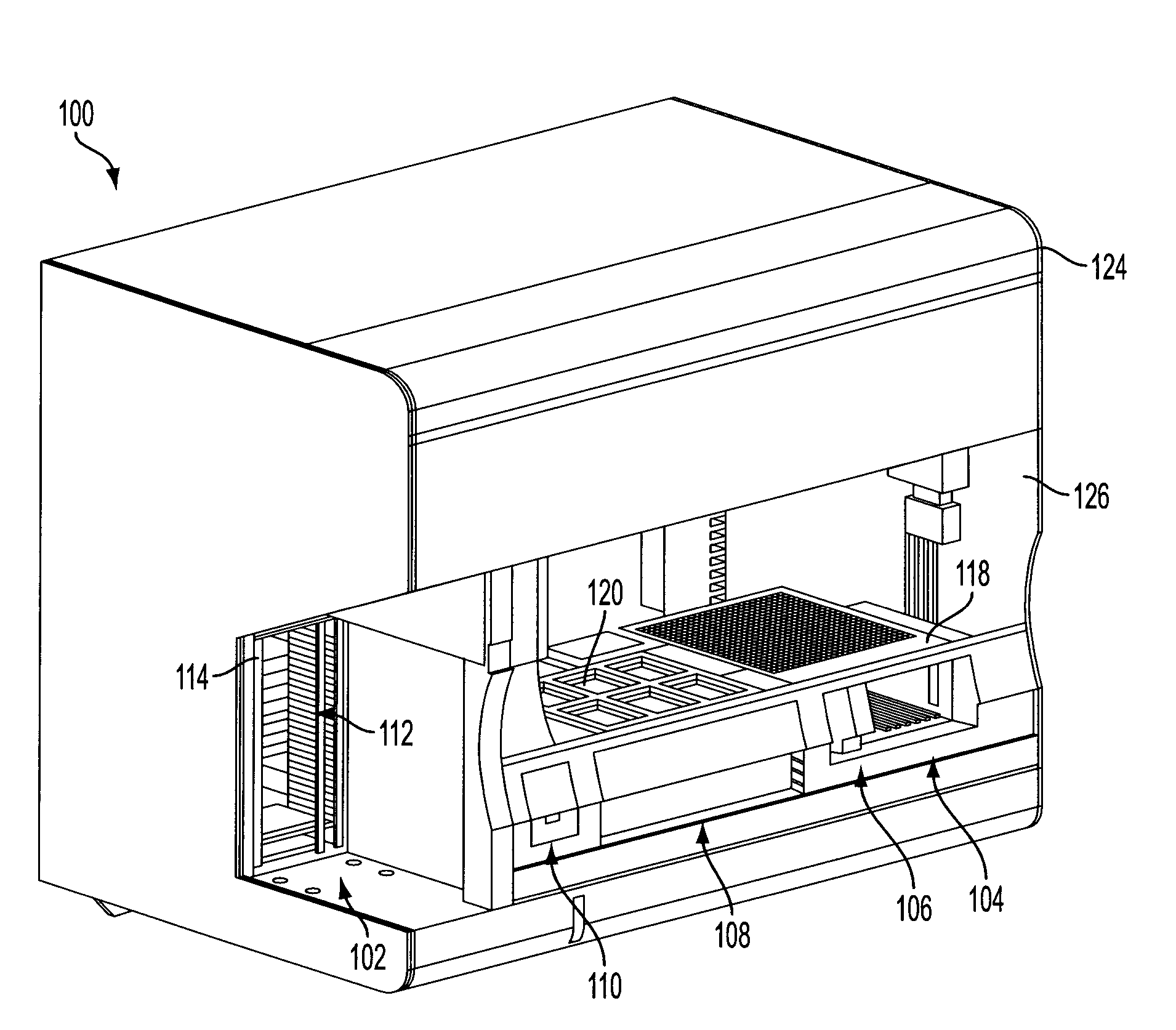
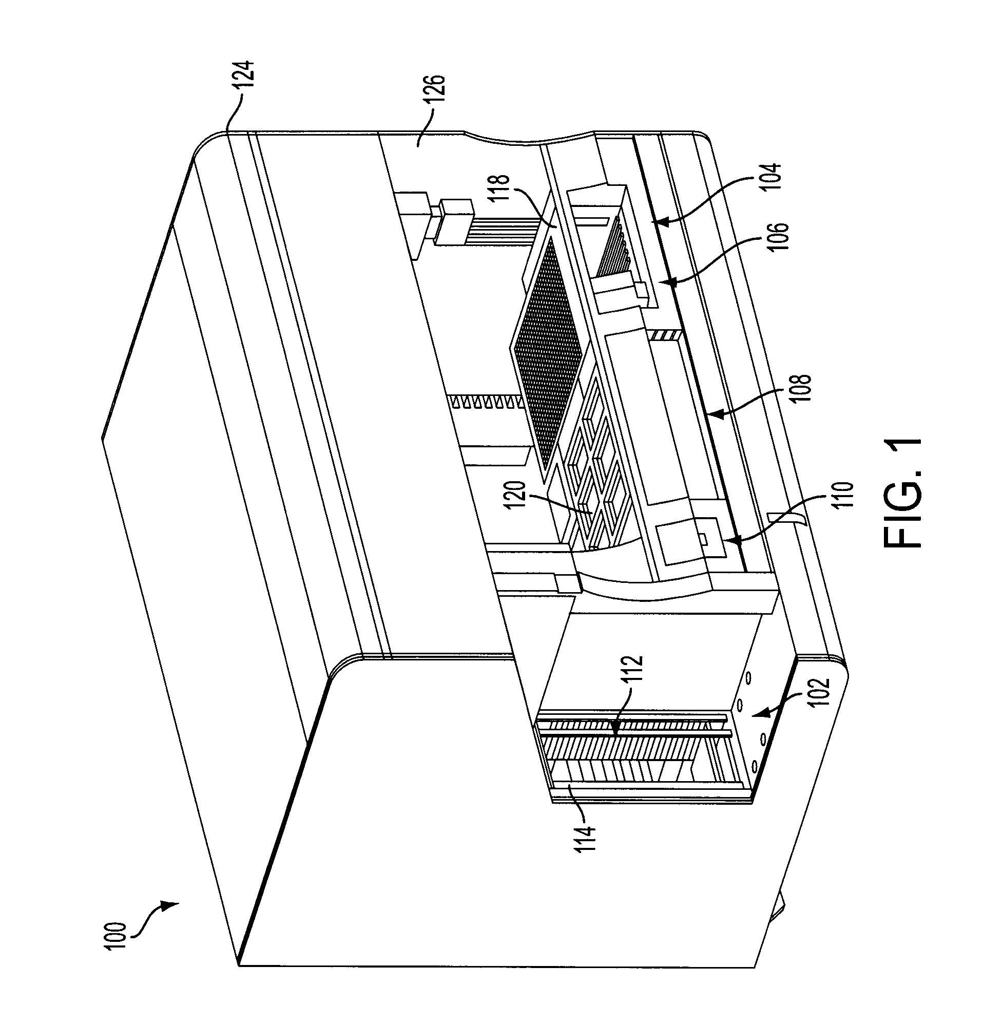
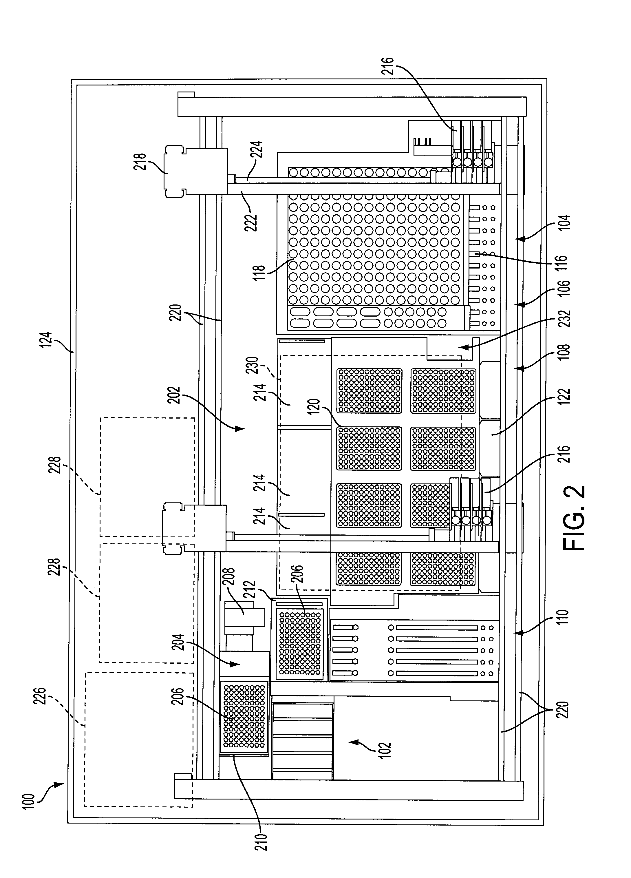
[0019]FIGS. 1-3 provide various views of an exemplary automated system in the form of an analytical system (“AS”) 100. FIG. 1 is an isometric view of the AS 100 showing the device with its exterior coverings in place. FIG. 2 is an overhead schematic view of the AS 100, generally showing the layout of various internal parts. FIG. 3 is an isometric vie...


PUM

PropertyMeasurementUnit
concentrationaaaaaaaaaa
diameteraaaaaaaaaa
pHaaaaaaaaaa

Abstract

A reagent cabinet for an automated processing apparatus. The reagent cabinet has a housing, and a drawer slidably mounted in the housing. The drawer has a lower deck adapted to receive a fluid reservoir, and an upper deck located above the lower deck and adapted to receive a fluid supply container. A supply connection hose is provided to selectively connect the fluid supply container to the fluid reservoir. A reservoir connection hose is provided to selectively connect to the fluid reservoir and to convey fluid from the fluid reservoir to a downstream location outside the cabinet. A pump is mounted on the drawer. The pump is adapted to convey fluid through either the supply connection hose or the reservoir connection hose.

Description

CROSS-REFERENCE TO RELATED APPLICATIONS[0001]This application is related to and claims the benefit of U.S. application Ser. No. 12 / 622,162 filed Nov. 19, 2009 and U.S. Provisional Patent Application Ser. No. 61 / 242,694, filed Sep. 15, 2009, entitled “Automated sample processing systems and methods” (Attorney Docket No. 74708.000800), and both are incorporated by reference in their entirety.BACKGROUND[0002]1. Field of the Art[0003]The present disclosure relates to automated sample processing systems, and provides systems and methods that permit high-throughput specimen processing for samples that may be provided in various states of preparation.[0004]2. Description of Related Art[0005]Historically, biological samples being tested in the context of medical services have been processed using labor-intensive manual methods, or semi-automated methods requiring careful supervision by a laboratory technician. Such systems can be prone to operator error in many forms, such as improper testi...

Claims


Application Information

Patent Timeline
Patent Type & Authority Applications(United States)
IPC IPC(8): B01L99/00B65B3/04
CPCG01N35/028G01N35/1002Y02P20/582G01N35/1067Y10T137/474Y10T137/4807Y10T137/7032
Inventor MILLER, JONATHAN MATTHEWRAGIN, YANCY KENAN
Owner BECTON DICKINSON & CO
Learn More