
Analysis method, radiation imaging apparatus using analysis method, and analysis program for executing analysis method

a radiation imaging and analysis method technology, applied in the direction of optical radiation measurement, instruments, nuclear engineering, etc., can solve the problems of long time required for obtaining distortion which originally does not exist, and difficult to obtain an accurate weighting function and an accurate true phase value, so as to achieve quick and simple unwrapping and generate accurate weighting functions. , the effect of quick and simpl

Inactive Publication Date: 2011-06-30
CANON KK
View PDF1 Cites 13 Cited by
  • Summary
  • Abstract
  • Description
  • Claims
  • Application Information

AI Technical Summary

Benefits of technology

The present invention provides a method for generating an accurate weighting function quickly and simply and performing unwrapping quickly compared with Non Patent Citation 1. This makes it easier to analyze data from a radiation imaging apparatus and obtain a high-quality image of the detected object.

Problems solved by technology

When phase information including such a portion in which the phase changes discontinuously is unwrapped, a problem may occur in which an inconsistency occurs between the portion in which the phase changes discontinuously and a portion in which the phase changes continuously and thus distortion which originally does not exist appears.
The calculation method described above has a problem in that since iterative calculations are performed while a weighting function and a true phase value are corrected alternately, a long time is required for obtaining an accurate true phase value.
However, it is difficult to obtain an accurate weighting function and an accurate true phase value.

Method used


Image

  • Analysis method, radiation imaging apparatus using analysis method, and analysis program for executing analysis method
  • Analysis method, radiation imaging apparatus using analysis method, and analysis program for executing analysis method
  • Analysis method, radiation imaging apparatus using analysis method, and analysis program for executing analysis method

Examples


example

[0070]An example of the present invention will be explained. In this example, a case where calculation was performed using the analysis method described above for an X-ray phase imaging apparatus using the Talbot interferometer described above will be explained. The parameters described below were used.

[0071]Coherent hard X-rays having a wavelength of 0.7 Å at 17.7 keV was used. A silicone object having a cylindrical shape with a diameter of 0.256 mm and a height of 0.1 mm was used as an object to be detected. FIG. 7 is a sectional view of the cylindrical silicone object. X-rays were applied to the cylindrical silicone object in parallel to the central axis of the cylinder (the axis connecting the centers of two circles on the sides of the cylinder). The range for which calculations were performed was a range of 0.512 mm squares, and the center of the square coincided with the central axis of the cylindrical silicone object. A phase grating and an absorption grating having a pitch o...


PUM


Abstract

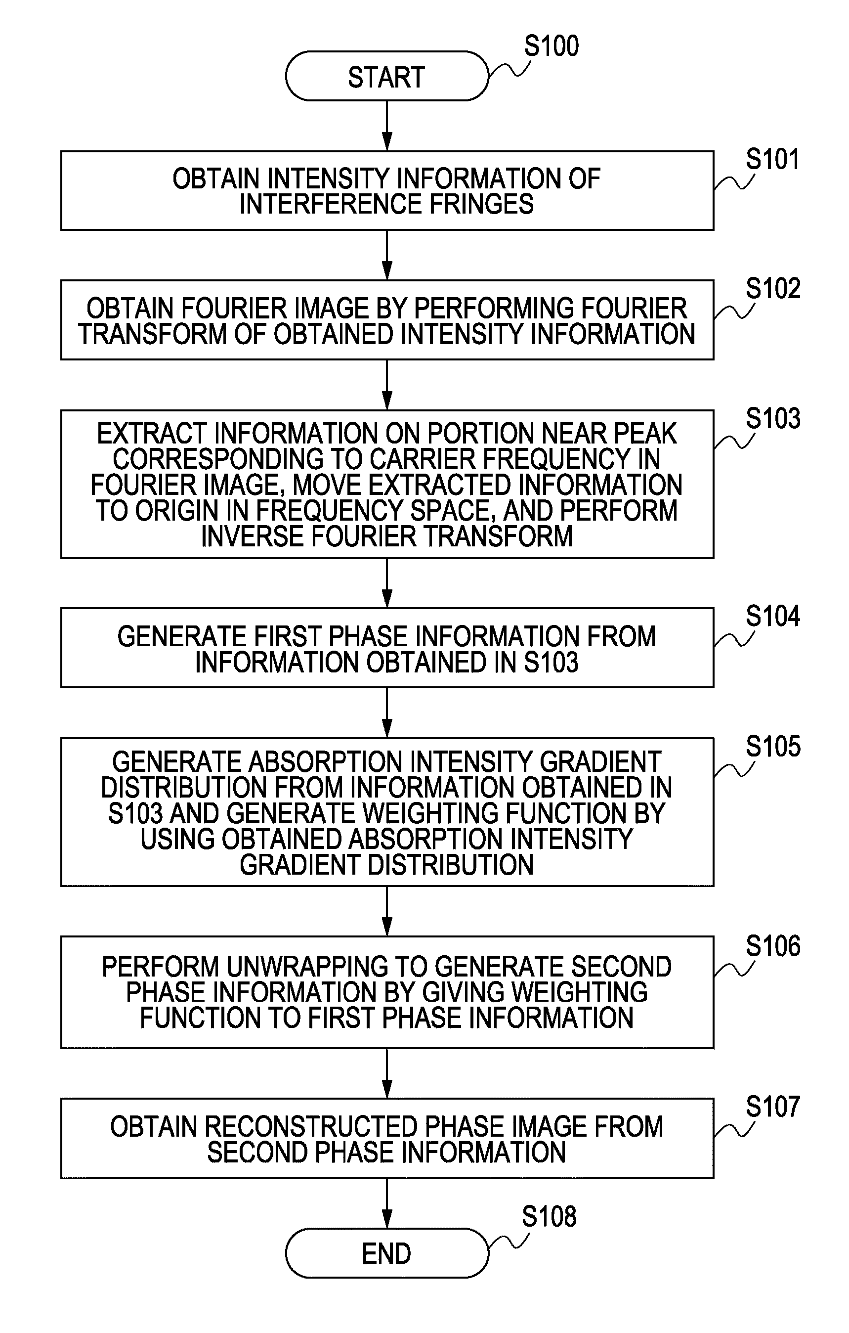
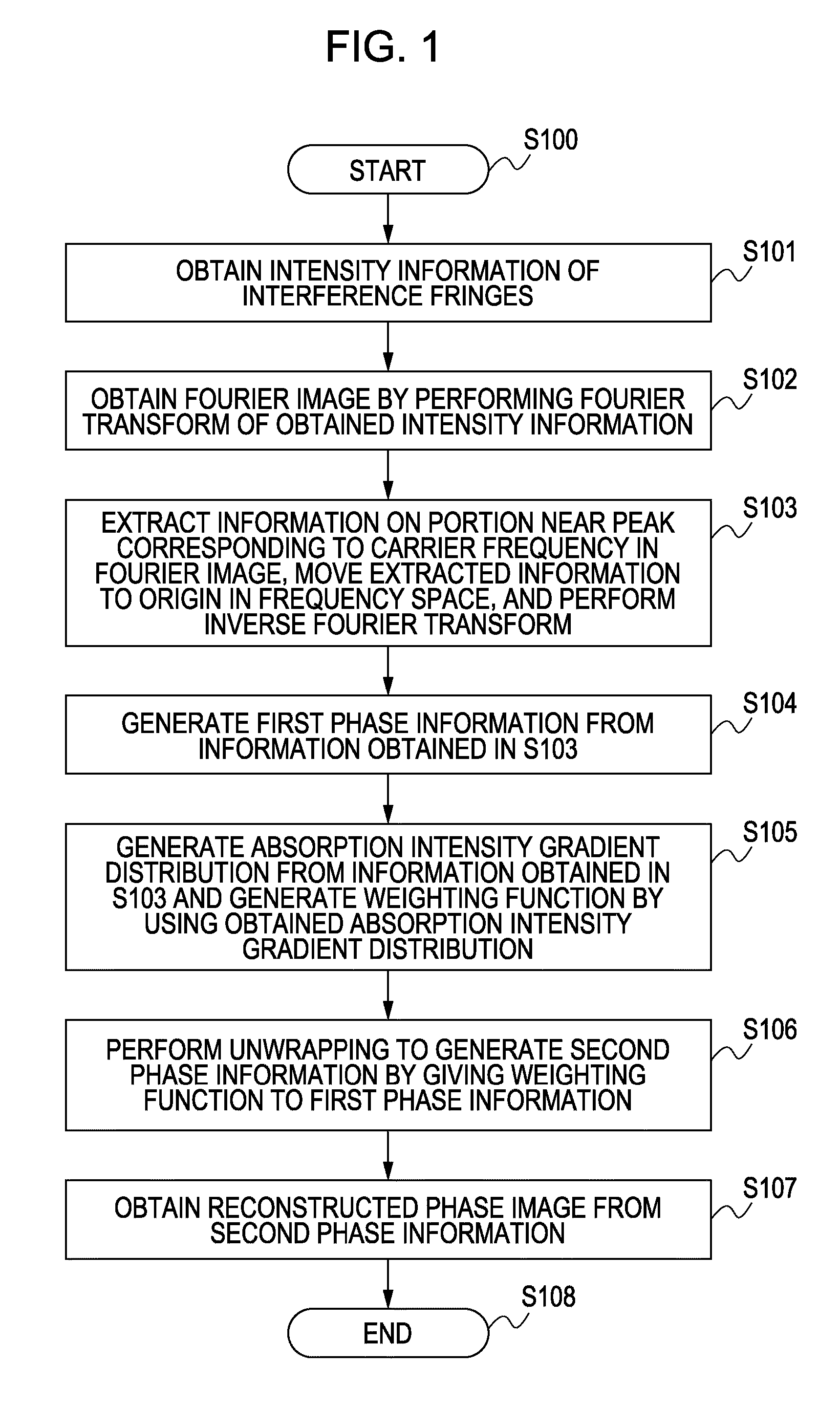
An analysis method for use in a radiation imaging apparatus employing intensity information of interference fringes of radiation rays that have passed through a detected object includes the steps of generating first phase information of the detected object wrapped into a range of 2π from the intensity information of the interference fringes; generating information on an absorption intensity gradient of the detected object from the intensity information of the interference fringes; generating a weighting function on the basis of an absolute value of a gradient in the information on the absorption intensity gradient; and generating second phase information by unwrapping the first phase information by using the weighting function.

Description

TECHNICAL FIELD[0001]The present invention relates to an analysis method, a radiation imaging apparatus using the analysis method, and an analysis program for executing the analysis method.BACKGROUND ART[0002]X-rays, which are an example of radiation rays, are used in imaging methods in areas of industry, such as non-destructive inspection of the inside of materials, in areas of medical images, such as X-ray photography and X-ray computed tomography (CT), and in other areas. Examples of imaging methods employing X-rays include an absorption contrast method and a phase contrast method.[0003]In the absorption contrast method, an image of a detected object can be obtained by producing an absorption contrast on the basis of the attenuation in X-rays caused when the X-rays pass through the detected object.[0004]Meanwhile, in the phase contrast method, an image of a detected object can be obtained by producing a phase contrast on the basis of a phase change caused when X-rays pass through...

Claims


Application Information

Patent Timeline
Patent Type & Authority Applications(United States)
IPC IPC(8): G06K9/00
CPCG06T7/0002G21K2201/067G01N23/20075G01N2223/401G01N23/04G01J9/02G21K1/06A61B6/4291A61B6/484G21K2201/06G01N23/041
Inventor NAGAI, KENTARODEN, TORU
Owner CANON KK
Learn More