Apparatus for reinforcing railroad ties

a technology for reinforcing and railroad ties, applied in the direction of tracks, superstructures, constructions, etc., can solve the problems that rail ties cannot be easily and quickly installed at constant intervals, and achieve the effects of reducing the probability of rail deformation, reducing the chance of derailment, and increasing the speed of a train

Inactive Publication Date: 2011-06-30
RYU BONG SU
View PDF4 Cites 6 Cited by
  • Summary
  • Abstract
  • Description
  • Claims
  • Application Information

AI Technical Summary

Benefits of technology

[0012]The purpose of the present invention is to provide an apparatus for reinforcing railroad ties which can prevent rails from being deformed by a side-directional force which results from the centrifugal force of a train and / or a side-directional force which results from heat-expanded rails.
[0013]Another purpose of the present invention is to facilitate precise installation of railroad ties at a designated position at constant intervals and swift replacement of damaged railroad ties.
[0014]Another purpose of the present invention is to prevent a reinforcing plate from being separated upward due to vibration of a train by installing a rotary latch on top of railroad ties.
[0020]The apparatus for reinforcing railroad ties according to the present invention couples the reinforcing plate with the railroad ties such that the area which the track ballast contacts is increased. Therefore, the present invention can prevent the rails from being deformed due to the deformation or movement of the railroad ties because the supporting force which is applied to the railroad ties against the side-directional force is reduced by the amount of the supporting force applied to the reinforcing plate. Since the present invention can remove the probability of rail deformation, the speed of a train can be increased and the chance of derailment can be reduced.
[0021]When railroad ties are damaged or rails need to be repaired, the reinforcing plate can be easily installed and removed due to the coupling system of the present invention, which can reduce maintenance costs for railroad tracks.
[0022]Furthermore, the rotary latch can prevent the reinforcing plate from being separated upward due to vibration of a train.

Problems solved by technology

Furthermore, there has been a problem in conventional railroad tracks that the railroad ties cannot be easily and swiftly installed at constant intervals.

Method used


Image

  • Apparatus for reinforcing railroad ties
  • Apparatus for reinforcing railroad ties
  • Apparatus for reinforcing railroad ties

Examples


Embodiment Construction

[0031]Hereinafter, an apparatus for reinforcing railroad ties according to an embodiment of the present invention will be explained in more detail with reference to the accompanying drawings.

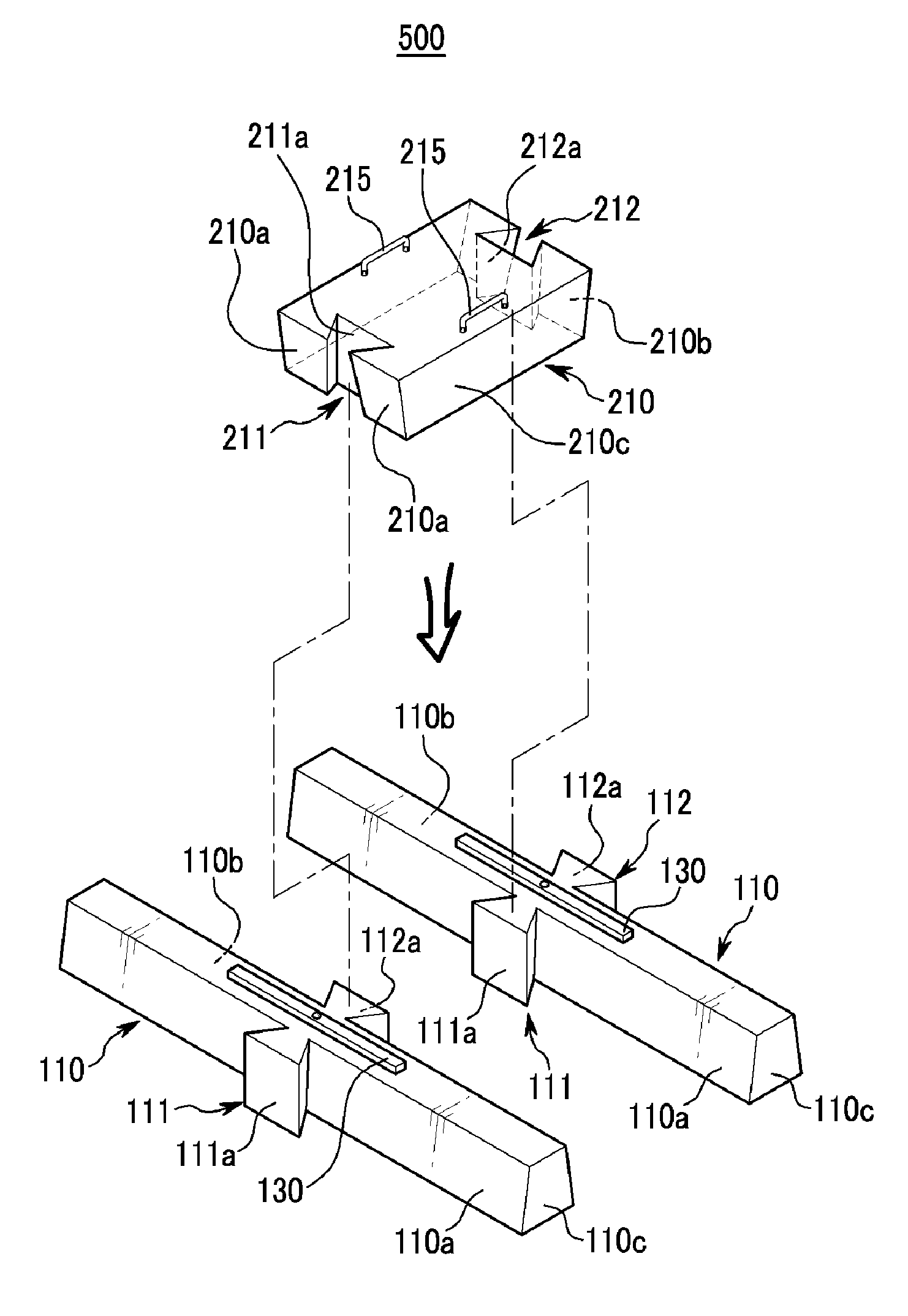
[0032]FIG. 4 is an exploded view of the apparatus for reinforcing railroad ties according to an embodiment of the present invention. FIG. 5 is a perspective view of the apparatus for reinforcing railroad ties according to an embodiment of the present invention. FIG. 6 is a side view of the apparatus for reinforcing railroad ties according to an embodiment of the present invention. FIG. 7 is a perspective view of the apparatus for reinforcing railroad ties according to an embodiment of the present invention, which is installed in a curved railroad track. FIG. 8 is a schematic view of the supporting force distribution of the apparatus for reinforcing railroad ties according to an embodiment of the present invention.

[0033]The apparatus for reinforcing railroad ties 500 comprises railroad ties 110 h...


PUM


Abstract

The present invention comprises a railroad tie disposed below the rails to support the rails and comprising a protrusion on a sloped surface of the railroad tie; and a reinforcing plate comprising a groove on a sloped surface of the reinforcing plate, which corresponds to the sloped surface of the railroad tie, wherein the reinforcing plate is coupled with the railroad ties by inserting the protrusion into the groove and opposing the sloped surface of the reinforcing plate to the sloped surface of the railroad tie.

Description

BACKGROUND OF THE INVENTION[0001]1. Field of the Invention[0002]The present invention relates to an apparatus for reinforcing railroad ties and particularly an apparatus for reinforcing railroad ties which disperses a force applied to the side of a railroad tie, thereby preventing railroad ties and / or rails from being deformed or broken and holding rails to the correct gauge, and facilitates installation and repair of railroad ties.[0003]2. Description of the Related Art[0004]FIG. 1 is a cross-sectional view of a conventional railroad track including track ballast 10, rails 20 and railroad ties 30. FIG. 2 is a perspective view of a conventional railroad track.[0005]The railroad ties 30 are members generally laid transverse to the rails 20 and spaced apart from each other, on which the rails 20 are supported and fixed, to transfer the loads from rails 20 to the track ballast 10 and subgrade, and to hold the rails 20 to the correct gauge. Railroad ties 30 have traditionally been made ...

Claims


Application Information

Patent Timeline
Patent Type & Authority Applications(United States)
IPC IPC(8): E01B3/00E01B3/36
CPCE01B1/007E01B3/48E01B3/28E01B3/00
Inventor RYU, BONG SU
Owner RYU BONG SU
Why Eureka
Try Eureka