
Information recording medium and playback device for playing back 3D images

a technology of information recording medium and playback device, which is applied in the direction of instruments, television systems, signal generators with optical-mechanical scanning, etc., can solve the problems of deteriorating screen use efficiency, user inability to enjoy the stereoscopic effect to the full, and extremely difficult to view the stereoscopic image playback, etc., to improve the screen use efficiency and improve the stereoscopic effect.

Active Publication Date: 2011-06-23
PANASONIC CORP
View PDF8 Cites 76 Cited by
  • Summary
  • Abstract
  • Description
  • Claims
  • Application Information

AI Technical Summary

Benefits of technology

[0010]The additional information including a region-saving flag defining a display region of a subtitle is included in a stream selection table for each playback section in correspondence with a stream number. When the playback section changes, or when a request for changing the stream is received, a stream selection procedure is executed. A stream number in accordance with the language settings of a playback device is set in a stream number register. As a result, a region-saving flag indicated by a piece of additional information corresponding to the set stream number is provided with the playback device. With this structure, it is possible to realize control in which a display region of a subtitle is saved in the upper end of the screen in a playback section and a display region of a subtitle is saved in the lower end of the screen in another playback section.
[0011]The cinema scope size (1:2.35) is generally used for the aspect ratio of video of movies. In the case where a video is stored in an optical disc such as a BD-ROM, a main feature video is disposed in the center of an HD video having the aspect ratio of 16:9 without changing the aspect ratio, and a black frame is inserted into each of the upper side and the lower side of the HD video. Accordingly, with the above structure, it is possible to display subtitles in a large subtitle display region generated by collecting black frames located above and below the main feature video to one of the upper end and the lower end of the video plane. This can improve the use efficiency of the screen, thereby improving the stereoscopic effect.Additional

Problems solved by technology

This results in playback of a stereoscopic image that is extremely difficult to view.
Accordingly, if any one of the ends of the screen is uniformly fixed as a subtitle display region, the use efficiency of the screen is deteriorated.
As a result, even if a user spends his money to purchase an expensive widescreen 3D TV, there might occur a case where the user cannot enjoy the stereoscopic effect to the full.

Method used


Image

  • Information recording medium and playback device for playing back 3D images
  • Information recording medium and playback device for playing back 3D images
  • Information recording medium and playback device for playing back 3D images

Examples


embodiment 1

[0135]Embodiment 1 is characterized in that a register in the playback device stores information that indicates whether or not the playback device has a capability to realize a stereoscopic viewing using a right-eye graphics stream and a left-eye graphics stream.

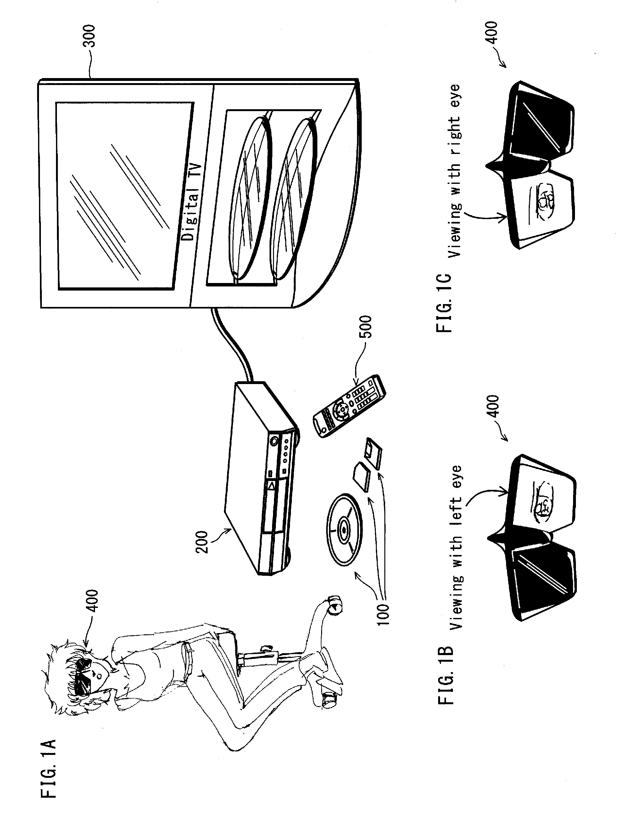
[0136]In the following description, the main-view and the sub-view are used to realize the parallax image method. The parallax image method (also called 3D-LR mode) is a method for realizing the stereoscopic viewing by preparing separately an image for the right eye and an image for the left eye, and causing the image for the right eye to enter only into the right eye and the image for the left eye enter only into the left eye. FIG. 2 shows the user's head on the left side of the drawing and the images of a dinosaur skeleton seen respectively by the left eye and the right eye of the user on the right side of the drawing. When the light transmission and block are repeated alternately for the left and right eyes, the left and ...

modification example

[0588]As a modification example of the present embodiment, the following describes a method of shifting upward or downward not only picture data stored in the video plane memory but also subtitles stored in the PG plane memory so as to overlay the picture data with the subtitles.

[0589]FIGS. 35A through 35C show the stream registration sequences in the extension stream selection table according to the present modification example. FIG. 35B shows the internal structure of the PG stream registration sequence.

[0590]In the present modification example, the stream registration information of the PG stream additionally includes a “PG shift value video shift upward (PG_v_shift_value_for_Up)” and a “PG shift value video shift downward (PG_v_shift_value_for_Down)”.

[0591]The “PG shift value in video shift upward (PG_v_shift_value_for_Up)” represents an amount of downward shift of subtitle data stored in the PG plane memory in the case where the video shift mode is set as “Up” and a display reg...

embodiment 2

[0597]The following describes Embodiment 2 of the present invention.

[0598]In the present embodiment, a method is described for realizing 3D video having an appropriate depth depending on the screen size of a TV connected to the 2D / 3D playback device.

[0599]In the case of 3D video with use of the parallax images, the screen size affects the sense of depth of 3D video, as shown in the left side of FIG. 40. This is due to the difference value between the left-eye video and the right eye video that varies depending on the screen size of the TV. Suppose that, for example, in the case where a left video and a right video are created so as to realize the most appropriate width for a 50-inch TV as shown in the left side of FIG. 40. In such a case, it is possible to realize the most appropriate viewing for a 50-inch TV. However, the difference value between the left-eye video and the right eye video is small for a TV smaller than the 50-inch TV, and as a result a video that is not powerful an...


PUM

PropertyMeasurementUnit
current streamaaaaaaaaaa
screen sizeaaaaaaaaaa
sizeaaaaaaaaaa

Abstract

To aim to increase the use efficiency of a screen on which a subtitle is displayed together with a stereoscopic image. A video shift mode is set for each subtitle. When a stereoscopic image is played back, in accordance with the video shift mode of the subtitle, a video plane is shifted upward or downward to perform cropping processing of collecting black frames provided in the upper end and the lower end of the screen in either one of the upper end and the lower end so as to save a display region of the subtitle.

Description

TECHNICAL FIELD[0001]The present invention relates to a technology of playing back 3D and 2D images.BACKGROUND ART[0002]The 2D images, also called monoscopic images, are represented by pixels on an X-Y plane that is applied to the display screen of the display device. In contrast, the 3D images have a depth in the Z-axis direction in addition to the pixels on the X-Y plane applied to the screen of the display device.[0003]The 3D images are presented to the viewers (users) by simultaneously playing back the left-view and right-view images to be viewed respectively by the left and right eyes so that a stereoscopic effect can be produced. The users would see, among the pixels constituting the 3D image, pixels having positive Z-axis coordinates in front of the display screen, and pixels having negative Z-axis coordinates behind the display screen.[0004]It is preferable that an optical disc storing a 3D image has compatibility with a playback device that can play back only 2D images (her...

Claims


Application Information

Patent Timeline
Patent Type & Authority Applications(United States)
IPC IPC(8): H04N5/92H04N9/80G11B20/10H04N5/91H04N5/93H04N13/00H04N13/04
CPCG11B27/3027G11B2220/2541H04N5/775H04N5/85H04N9/7921H04N9/8042H04N19/597H04N9/8205H04N9/8211H04N9/8227H04N13/0003H04N13/0055H04N13/007H04N9/8063H04N13/10H04N13/183H04N13/189H04N5/445H04N5/92
Inventor SASAKI, TAIJIYAHATA, HIROSHIOGAWA, TOMOKI
Owner PANASONIC CORP
Learn More