Variable electric field strength metal and metal oxide microplasma lamps and fabrication

a microplasma lamp and variable electric field technology, applied in the field of microcavity plasma devices, can solve the problems of increased manufacturing costs, short life of early microcavity plasma devices, and more expensive materials and fabrication difficulties

Active Publication Date: 2011-06-23
THE BOARD OF TRUSTEES OF THE UNIV OF ILLINOIS
View PDF19 Cites 8 Cited by
  • Summary
  • Abstract
  • Description
  • Claims
  • Application Information

AI Technical Summary

Benefits of technology

[0011]Preferred embodiments of the invention provide microcavity plasma lamps having a plurality of metal and metal oxide layers defining a plurality of arrays of microcavities and encapsulated thin metal electrodes. Packaging encloses the plurality of metal and metal oxide layers in plasma medium. The metal and metal oxide layers are configured and arranged to vary the electric field strength and total gas pressure (E / p) in the lamp. The invention also provides methods of manufacturing a microcavity plasma lamp that simultaneously evacuate the volume within the packaging and a volume surrounding the packaging to maintain an insignificant or zero pressure differential across the packaging. The packaging is backfilled with a plasma medium while also maintaining an insignificant or zero pressure differential across the packaging.

Problems solved by technology

Early microcavity plasma devices exhibited short lifetimes because of exposure of the electrodes to the plasma and the ensuing damage caused by sputtering.
Polycrystalline silicon and tungsten electrodes extend lifetime but are more costly materials and difficult to fabricate.
If the interconnect technology is difficult to implement or if the interconnect pattern is not easily reconfigurable, then manufacturing costs are increased and potential commercial applications may be restricted.
While individual arrays can be joined with other arrays to form larger arrays, rapidly fabricating individual arrays having radiating areas that exceed approximately 100 cm2 is challenging.

Method used


Image

  • Variable electric field strength metal and metal oxide microplasma lamps and fabrication
  • Variable electric field strength metal and metal oxide microplasma lamps and fabrication
  • Variable electric field strength metal and metal oxide microplasma lamps and fabrication

Examples


Embodiment Construction

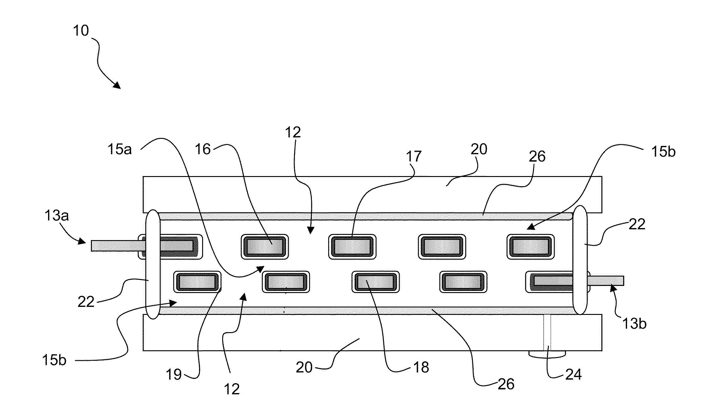
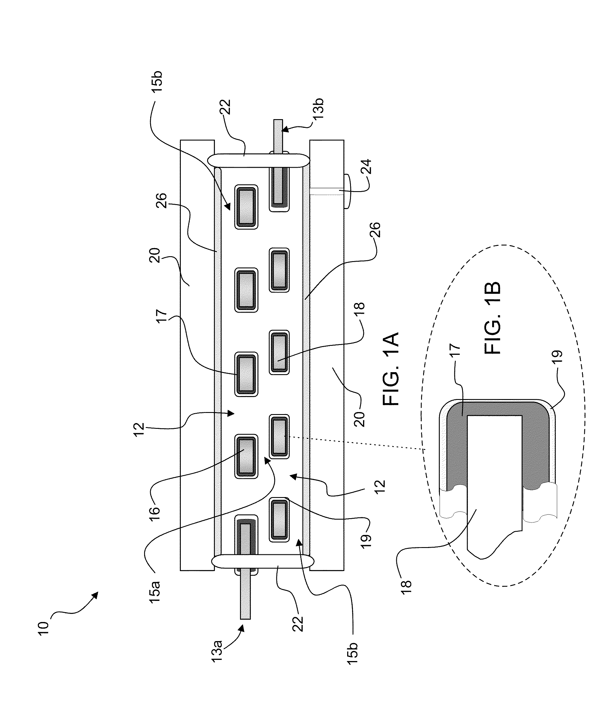
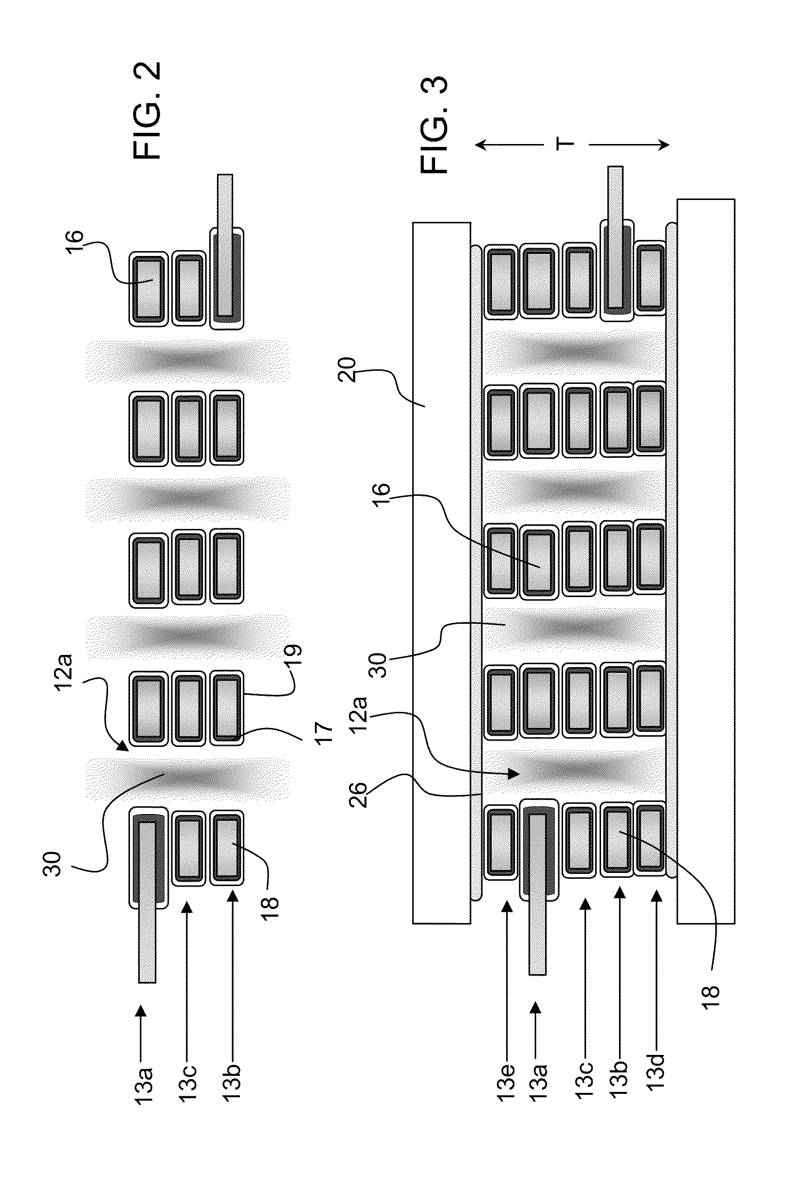
[0023]Preferred embodiments of the invention provide microcavity plasma lamps having a plurality of metal and metal oxide layers defining a plurality of arrays of microcavities and encapsulated thin metal electrodes. Packaging encloses the plurality of metal and metal oxide layers in plasma medium. The metal and metal oxide layers are configured and arranged to vary the electric field strength and total gas pressure (E / p) in the lamp. The invention also provides methods of manufacturing a microcavity plasma lamp that simultaneously evacuate the volume within the packaging and a volume surrounding the packaging to maintain an insignificant or zero pressure differential across the packaging. The packaging is backfilled with a plasma medium while also maintaining an insignificant or zero pressure differential across the packaging.

[0024]The invention provides high efficiency arrays of microcavity plasma devices including plural thin sheets of metal / metal oxide electrodes with associated...


PUM

PropertyMeasurementUnit
pressuresaaaaaaaaaa
diameteraaaaaaaaaa
areasaaaaaaaaaa

Abstract

Preferred embodiments of the invention provide microcavity plasma lamps having a plurality of metal and metal oxide layers defining a plurality of arrays of microcavities and encapsulated thin metal electrodes. Packaging encloses the plurality of metal and metal oxide layers in plasma medium. The metal and metal oxide layers are configured and arranged to vary the electric field strength and total gas pressure (E/p) in the lamp. The invention also provides methods of manufacturing a microcavity plasma lamp that simultaneously evacuate the volume within the packaging and a volume surrounding the packaging to maintain an insignificant or zero pressure differential across the packaging. The packaging is backfilled with a plasma medium while also maintaining an insignificant or zero pressure differential across the packaging.

Description

STATEMENT OF GOVERNMENT INTEREST[0001]This invention was made with Government assistance under U.S. Air Force Office of Scientific Research grant Nos. F49620-03-1-0391 and AF FA9550-07-1-0003. The Government has certain rights in this invention.FIELD OF THE INVENTION[0002]The invention is in the field of microcavity plasma devices, also known as microdischarge devices or microplasma devices.BACKGROUND[0003]Microcavity plasma devices produce a nonequilibrium, low temperature plasma within, and essentially confined to, a cavity having a characteristic dimension d below approximately 500 μm. This new class of plasma devices exhibits several properties that differ substantially from those of conventional, macroscopic plasma sources. Because of their small physical dimensions, microcavity plasmas normally operate at gas (or vapor) pressures considerably higher than those accessible to macroscopic devices. For example, microplasma devices with a cylindrical microcavity having a diameter o...

Claims


Application Information

Patent Timeline
Patent Type & Authority Applications(United States)
IPC IPC(8): H01J61/30H01J61/42H01J9/38
CPCH01J17/16H01J65/046H01J17/49
Inventor EDEN, J. GARYPARK, SUNG-JINREADLE, JASON D.YOON, JEKWONPRICE, ANDREWPUTNEY, JEFFREY
Owner THE BOARD OF TRUSTEES OF THE UNIV OF ILLINOIS
Why Eureka
Try Eureka