Intermediate housing of a gas turbine having an outer bounding wall having a contour that changes in the circumferential direction upstream of a supporting rib to reduce secondary flow losses

a gas turbine and intermediate housing technology, applied in the direction of liquid fuel engines, motors, engine control, etc., can solve the problems of degrading the efficiency of the fluid energy machine, increasing leakage, etc., and achieve the effect of efficient counteracting the formation and improving efficiency

Active Publication Date: 2016-07-05
MTU AERO ENGINES GMBH
View PDF17 Cites 5 Cited by
  • Summary
  • Abstract
  • Description
  • Claims
  • Application Information

AI Technical Summary

Benefits of technology

[0009]It is an object of the present invention to provide an intermediate housing which will make it possible to increase the efficiency.
[0012]The present invention makes it possible to efficiently counteract the formation of the dissipative secondary flow that develops in accordance with the related art in the cooling-air flow channel. Since it is possible to work with a smaller pressure differential between the gas flow and the cooling-air flow, the efficiency may be improved over the related art.

Problems solved by technology

In addition, in accordance with FIG. 2, the pressure fluctuation in the cavity leads to a greater pressure differential between gas flow 20 and cooling-air flow 21b, ultimately increasing leakage and resulting in a degraded efficiency of the fluid energy machine.

Method used


Image

  • Intermediate housing of a gas turbine having an outer bounding wall having a contour that changes in the circumferential direction upstream of a supporting rib to reduce secondary flow losses
  • Intermediate housing of a gas turbine having an outer bounding wall having a contour that changes in the circumferential direction upstream of a supporting rib to reduce secondary flow losses
  • Intermediate housing of a gas turbine having an outer bounding wall having a contour that changes in the circumferential direction upstream of a supporting rib to reduce secondary flow losses

Examples


Embodiment Construction

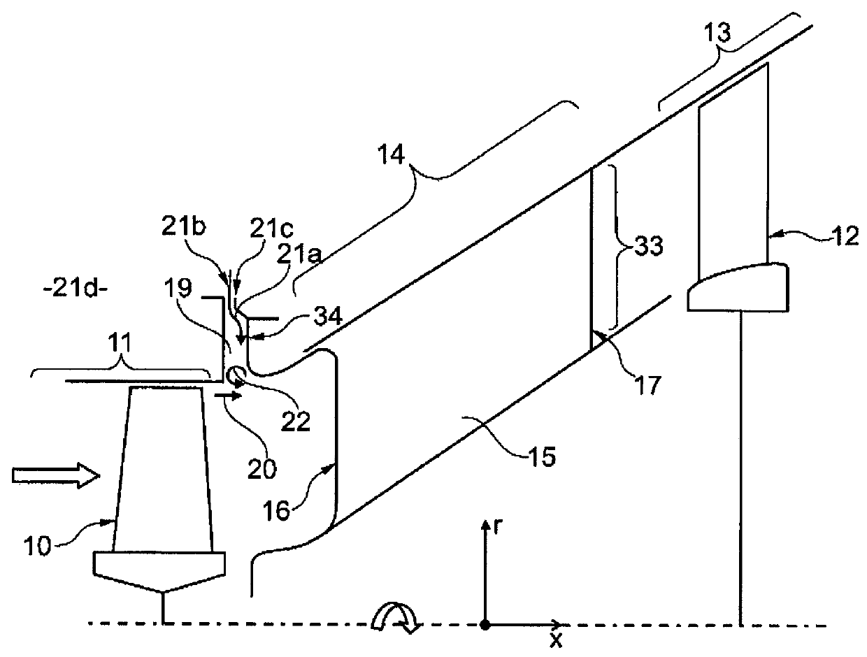
[0019]The present invention relates to the field of multi-shaft fluid energy machines, in particular, multi-shaft gas turbine engines, having a plurality of compressor components, as well as a plurality of turbine components. The basic design of such a fluid energy machine is familiar to one skilled in the art and has already been described in connection with FIG. 1.

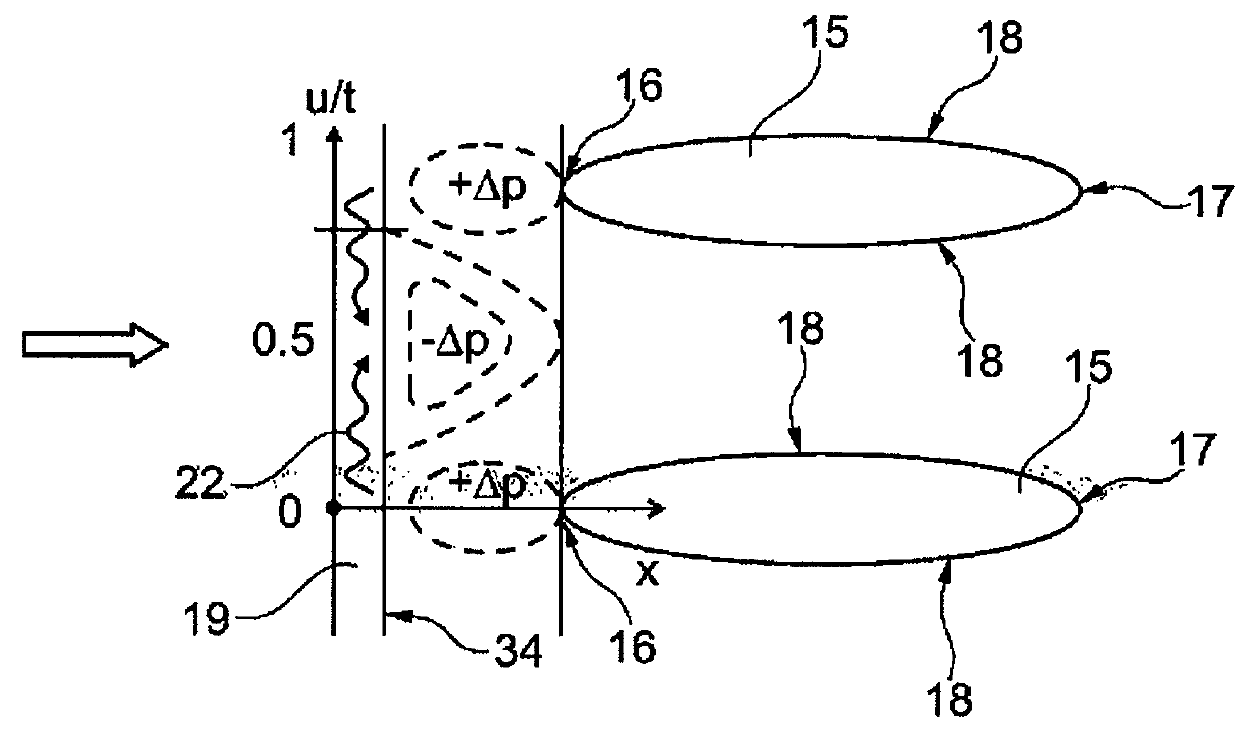
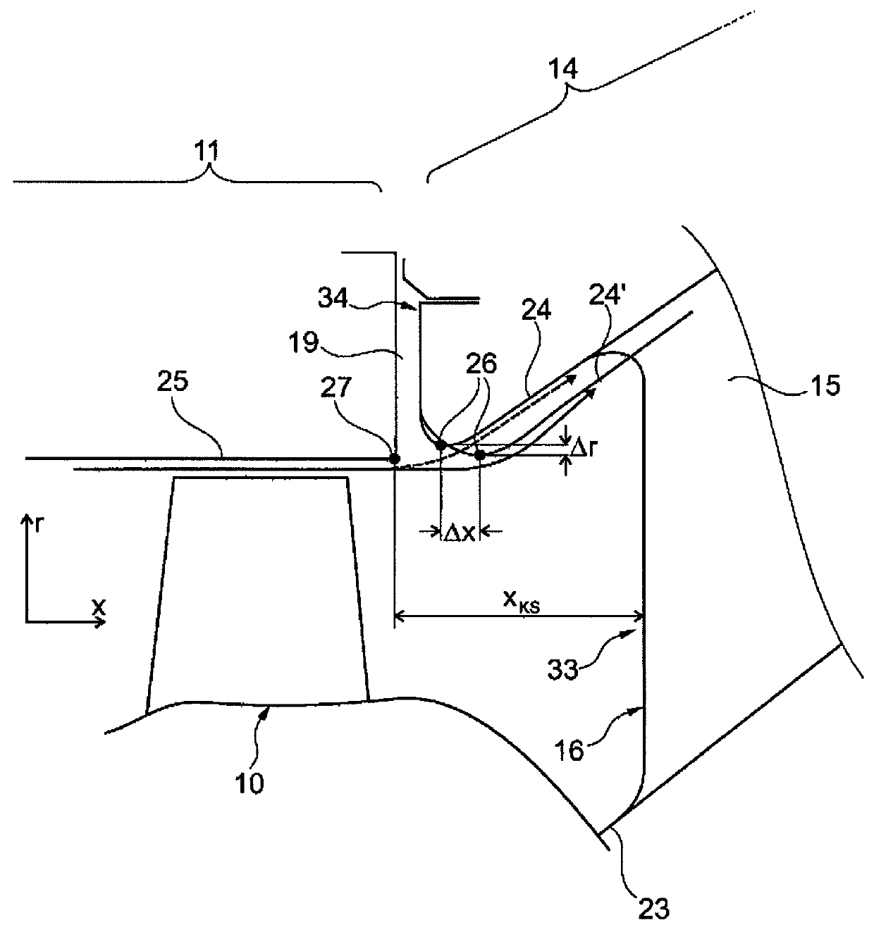
[0020]The present invention relates to details of an intermediate housing 14 of a fluid energy machine of this kind, which makes it possible to improve the entry of a cooling-air flow directed in a cooling-air flow channel 19 into the gas flow directed by crossflow channel 33 of intermediate housing 14, namely in an inlet zone of crossflow channel 33 upstream of supporting ribs 15 positioned in the same.

[0021]The present invention may be used both for an intermediate housing 14 of a dual-shaft fluid energy machine that extends between a high-pressure turbine 11 and a low-pressure turbine 13, as well as for an intermediat...


PUM


Abstract

Intermediate housing (14), in particular of turbines (11, 13) of a gas turbine engine, having a radially inner bounding wall (23) and having a radially outer bounding wall (24, 24′), having a crossflow channel (33), which is formed by the bounding walls (23, 24, 24′) and within which at least one supporting rib (15) is positioned that has a leading edge (16), a trailing edge (17), as well as side walls (18) extending between the leading edge (16) and the trailing edge (17) that direct a gas flow traversing the crossflow channel (33); the radially outer bounding wall (24) having a contour that changes in the circumferential direction at least in one section upstream of the supporting rib (15).

Description

[0001]The present invention relates to an intermediate housing, in particular of turbines of a gas turbine engine.BACKGROUND[0002]A multi-shaft fluid energy machine, for example, a multi-shaft gas turbine engine, has a plurality of compressor components, at least one combustion chamber and a plurality of turbine components. Thus, a dual-shaft gas turbine engine has a low-pressure compressor, a high-pressure compressor, at least one combustion chamber, a high-pressure turbine, as well as a low-pressure turbine. A triple-shaft gas turbine engine has a low-pressure compressor, a medium-pressure compressor, a high-pressure compressor, at least one combustion chamber, a high-pressure turbine, a medium-pressure turbine, and a low-pressure turbine.[0003]FIG. 1 shows a highly schematized detail of a multi-shaft gas turbine engine in the area of a rotor 10 of a high-pressure turbine 11, as well as of a rotor 12 of a low-pressure turbine 13. Extending between high-pressure turbine 11 and low-...

Claims


Application Information

Patent Timeline
Patent Type & Authority Patents(United States)
IPC IPC(8): F01D9/02F01D25/14F01D25/24F01D5/14
CPCF01D9/02F01D5/143F01D25/14F01D25/24F05D2240/11F05D2270/17
Inventor HOEGER, MARTINMAHLE, INGAGIER, JOCHEN
Owner MTU AERO ENGINES GMBH
Why Eureka
Try Eureka