
Rolling Vehicle Track

a technology for rolling vehicles and roller coasters, applied in the direction of rope railways, roads, building repairs, etc., can solve the problems of difficult bending or manipulation of rectangular tubing, severe structural integrity damage, and difficult processing of fabricating roller coaster tracks to a high degree of precision

Active Publication Date: 2011-06-23
ROCKY MOUNTAIN COASTERS
View PDF11 Cites 19 Cited by
  • Summary
  • Abstract
  • Description
  • Claims
  • Application Information

AI Technical Summary

Benefits of technology

[0078]Of course, ongoing research and development of embodiments of the present invention will likely confer additional details of manufacture and use, as well as other advantages, which may be disclosed in subsequent patent filings though not necessary be outside the scope of the present invention. The existence of such details, advantages or other aspects are not disclaimed in the present disclosure and, notwithstanding the brevity of the present disclosure, are expressly contemplated and included in the present disclosure.

Problems solved by technology

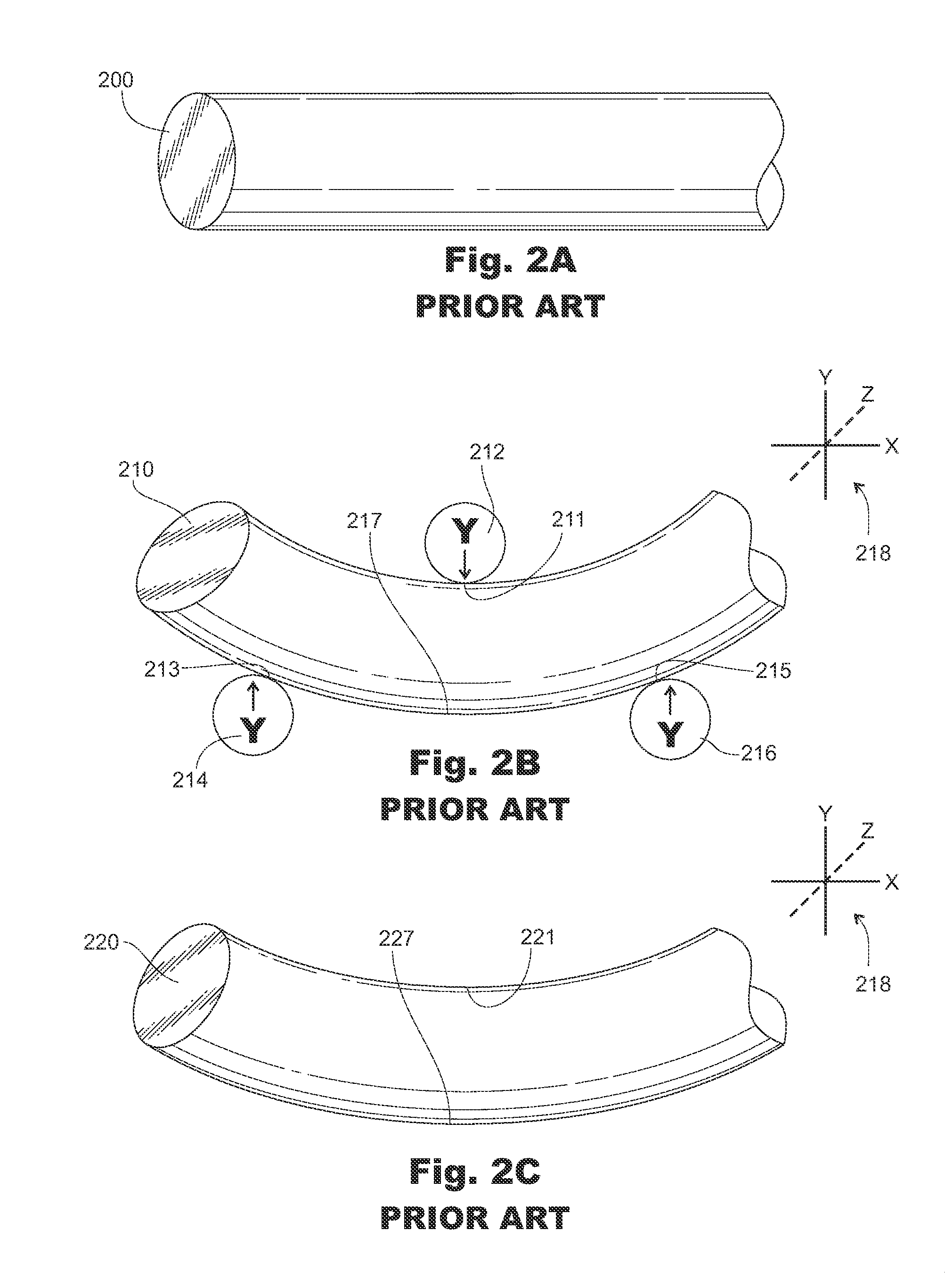
In this regard, the process of fabricating roller coaster tracks to a high degree of precision becomes very difficult as the amount of force and dynamics to bend the material in the pipe 200 cannot be exactly determined prior to the actual bending.
As such, being that the pipe 310 has been subjected to two bends with multiple compressions and expansions in the midsection of the pipe 310, its structural integrity is severely compromised.
While such a pipe could be advantageous over round pipe for roller coaster tracks, such rectangular tubing is difficult to bend or manipulate as further described.
Similarly, FIG. 4C is an illustration of the section of prior art rectangular tubing in FIG. 4A during a bending process in the Y dimension, thereby causing a failure in the integrity of the tubing.
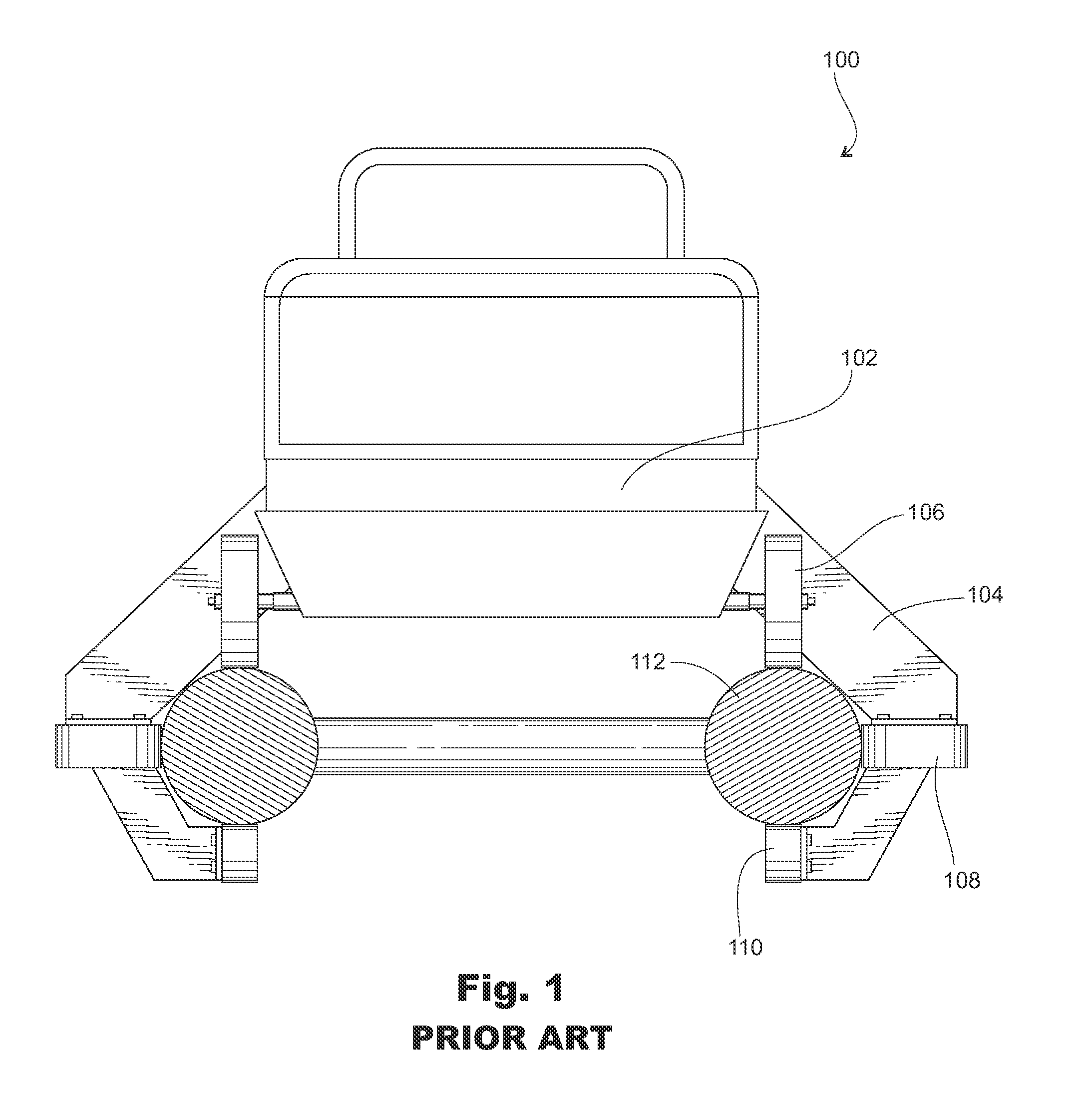
To name a few, without limitation, first, the material itself is expensive to utilize in round form.
Second, the material is difficult to properly bend into the desired form, often resulting in a “trial and error” approach to fabricating the desired tracks.
As shown in FIGS. 2A-2C and FIGS. 3A-3C, this process of manufacture also infuses stresses and ultimately weaknesses in the track material.
Third, the material (e.g. steel) is less structurally strong when placed in a round form such as a rod or a pipe, when compared to triangular, rectangular, I-beam or other forms.
Unfortunately, as depicted in FIGS. 4A-4C, utilizing rectangular (or other forms such as triangular or I-beam) tubing, while structurally more efficient than round rod or pipe in straight pieces, are far more complex to bend into curves.
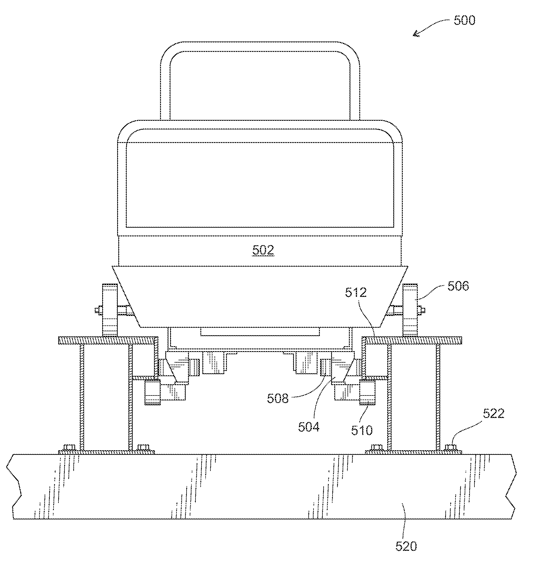
Using prior art or traditional methods, the one or more elongated, curved structures 1002 would be difficult to manufacture or fabricate, as the structures are comprised of rectangular cross-section shape and would not lend themselves to bending.

Method used


Image

  • Rolling Vehicle Track
  • Rolling Vehicle Track
  • Rolling Vehicle Track

Examples


Embodiment Construction

[0030]In the following description, for the purposes of explanation, specific details are set forth in order to provide a thorough understanding of the invention. However, it will be apparent that the invention can be practiced without these specific details. In other instances, well-known structures and devices may be depicted in block diagram form in order to avoid unnecessary detail of the invention relating to the corresponding discussion; and similarly, steps in the disclosed method may be depicted in flow diagram form. Section titles and references appearing within the following paragraphs are intended for the convenience of the reader and should not be interpreted to restrict the scope of the information presented at any given location.

[0031]The unique elongated, curved structures and fabrication and use thereof described herein comprise a plurality of advancements within various scopes in the amusement park, people moving, architectural and fabrication arts. As such, various...


PUM

PropertyMeasurementUnit
dimensionsaaaaaaaaaa
shapesaaaaaaaaaa
complex structuresaaaaaaaaaa

Abstract

A method of fabricating an amusement park ride track utilizing stock, planar materials, namely comprising of creating elongated, curved structures from planar materials. A roller coaster track capable of being fabricated from multiple planar pieces without heating or bending. Other embodiments are described which utilize elongated, curved structures such as ski lifts, people movers, staircases and architectural structures. A jig is disclosed for providing for ease of manufacture of the elongated, curved structures.

Description

CROSS REFERENCE TO RELATED APPLICATIONS[0001]This application claims priority to the earlier provisional application entitled “Improved Rolling Vehicle Track” filed Sep. 11, 2009 and having Ser. No. 61 / 241,785. The disclosures of the above related applications are hereby incorporated herein by reference in their entirety.TECHNICAL FIELD[0002]The present invention pertains to an improved rolling vehicle track and its manufacture. More particularly, preferred embodiments of the present invention pertain to an improved method of designing and manufacturing amusement park track that comprises affixing a plurality of planar materials to form a track rather than the conventional methods of bending straight track. Methods of use of the improved track are also included. Other alternate embodiments of the invention comprise other complex structures such as ski lifts, people movers and staircases.BACKGROUND[0003]Roller coasters, other amusement park rides, ski lifts and other rolling vehicle ...

Claims


Application Information

Patent Timeline
Patent Type & Authority Applications(United States)
IPC IPC(8): A63G7/00B61B13/00E04B1/38E04F11/02B23P11/00
CPCY10T29/49826A63G7/00A63G21/04
Inventor SCHILKE, ALANGRUBB, FREDBACHTAR, DODY
Owner ROCKY MOUNTAIN COASTERS
Learn More