
Apparatus, Components and Operating Methods for Circulating Fluidized Bed Transport Gasifiers and Reactors

a technology of fluidized bed and apparatus, which is applied in the direction of combustible gas production, combustible gas purification/modification, and combustion types, etc., can solve the problems of reducing the overall process efficiency, unable to use the apparatus in an atmospheric application, and large operating costs, so as to achieve the effect of improving conversion

Active Publication Date: 2011-06-23
SOUTHERN COMPANY SERVICES
View PDF8 Cites 89 Cited by
  • Summary
  • Abstract
  • Description
  • Claims
  • Application Information

AI Technical Summary

Benefits of technology

"The invention provides an improved apparatus for gasifying low rank coals in a circulating fluid bed reactor called a transport gasifier. The gasifier uses a distribution system, mixing zone, riser, and two cyclones to distribute and collect the gasification agent. The design of the apparatus reduces failures and maintenance costs associated with previous gasifiers. The gasification agent can be injected at the cyclone exits to increase the gas outlet temperature and reduce carbon content in the fly ash. The transport gasifier also allows for a more optimal configuration of aeration nozzles. Overall, the invention provides a reliable and efficient apparatus for gasifying low rank coals."

Problems solved by technology

In general, low rank coals contain more than 30% moisture; to dry the coals to less than 5% moisture requires an expensive drying facility with large operating costs, decreasing the overall process efficiency.
However, the apparatus can only be used in an atmospheric application and requires a large foot-print to produce the large amount of synfuel required by a modern chemical or power plant where coal gasifiers are installed.
How to separate the coal ash generated in the process from the heat carrying materials is one of the issues that are very difficult to deal with and the patent avoids the issue.
The minimum gas velocities necessary to entrain circulating solid particles from the Mixing zone causes the gas velocities to be unusually high in the Transport riser, leading to rapid erosion of any internals such as thermowells and erosion of the cyclone wall.
Further, as the pyrolysis reaction needs a much longer residence time for completion and prevent tar formation in the product synthesis gas (syngas), the Riser has to be impractically tall in a commercial process for the reactor proposed in the patent.
Also, this process does not teach how to distribute the gas (steam and air or oxygen) appropriately across the cross-section of a commercial size gasifier.
However, the moving bed gasifier requires lump coal as feed and cannot utilize the coal fines which are in abundance that often has few users nearby.
Another drawback of this technology is that much of the coal is converted into tar rather than useful syngas.
Moreover, all these gasifiers have complicated internals.
The fluidized bed gasifiers have various types of complicated internal gasification agent distributors which are made of exotic alloys to tolerate the gasifier operating temperatures up to 1100° C. In spite of considerable efforts in designing the distribution grids and selecting expensive high temperature alloy materials, failures of these grids still occur which is commercially unacceptable.
In the case of entrained flow gasifiers, the most problematic internal is the coal burner which is one of the most maintenance intensive items in the process.

Method used


Image

  • Apparatus, Components and Operating Methods for Circulating Fluidized Bed Transport Gasifiers and Reactors
  • Apparatus, Components and Operating Methods for Circulating Fluidized Bed Transport Gasifiers and Reactors
  • Apparatus, Components and Operating Methods for Circulating Fluidized Bed Transport Gasifiers and Reactors

Examples


example

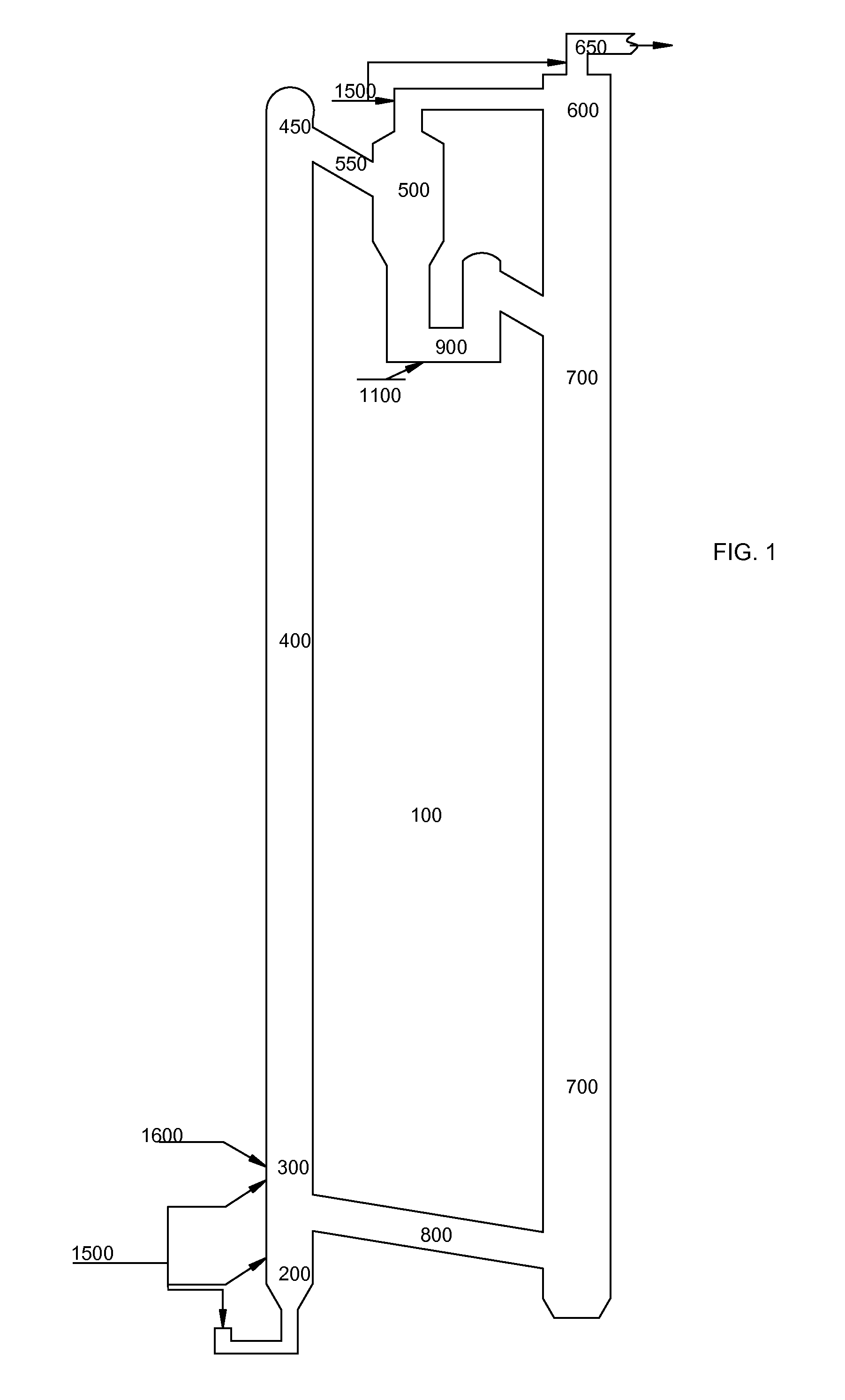
[0057]Described below is one non-limiting example of an engineering scale test unit of the transport gasifier illustrated in FIG. 1 that was built and extensively tested. None of the descriptions, ranges, or other information in this example should be considered to limit the scope of the disclosure above. The test unit gasifier has a nominal coal feed rate between 3,000 and 6,000 lbs / hr and uses both air and oxygen as the oxidant to react with char carbon in circulating solids to provide heat for the gasification reactions. Prior to tests with coal in the engineering scale unit, various embodiments of the transport gasifier were first tested in a large cold flow test unit with similar configuration. A number of different low rank coals were tested. The start-up solids inventory comprised coarse ash drained from the gasifier from a previous test run. The material in the solids stream at the test facility occasionally comprised sand with a mean particle size of 100-120 microns. Over a...


PUM

PropertyMeasurementUnit
angleaaaaaaaaaa
heightaaaaaaaaaa
velocityaaaaaaaaaa

Abstract

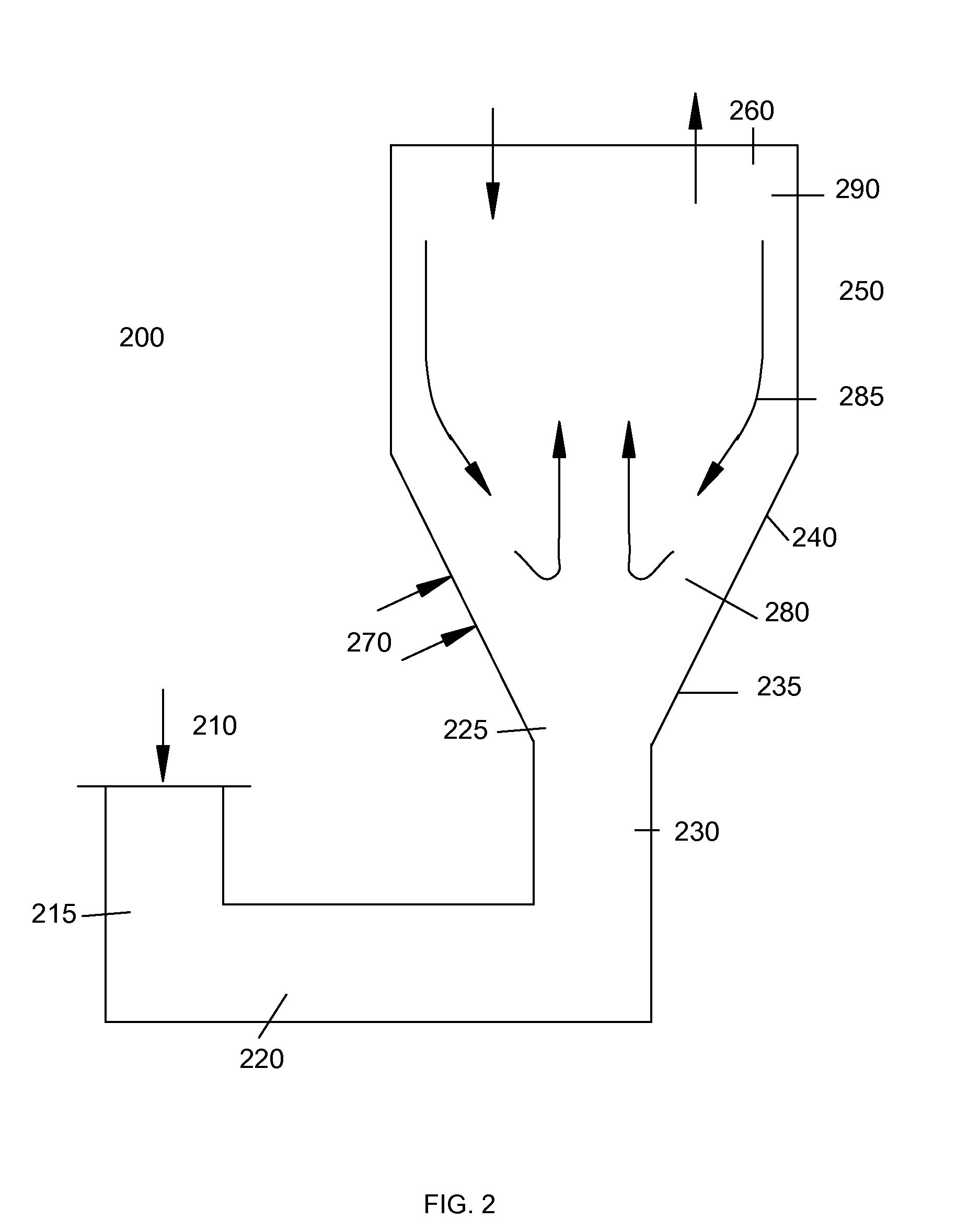
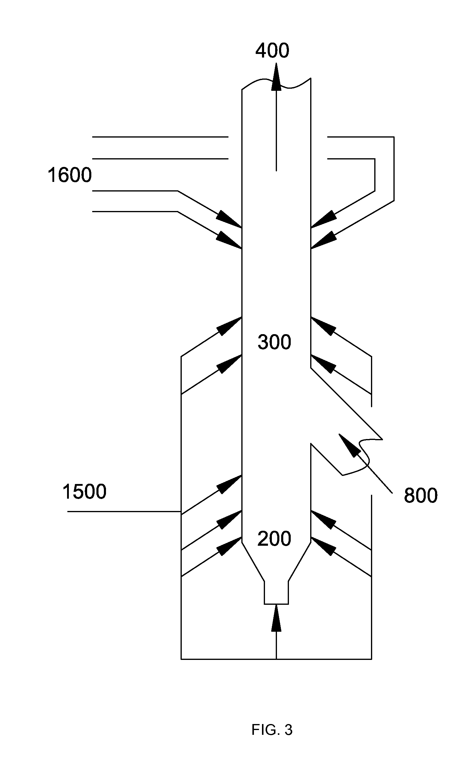
The improvements proposed in this invention provide a reliable apparatus and method to gasify low rank coals in a class of pressurized circulating fluidized bed reactors termed “transport gasifier.” The embodiments overcome a number of operability and reliability problems with existing gasifiers. The systems and methods address issues related to distribution of gasification agent without the use of internals, management of heat release to avoid any agglomeration and clinker formation, specific design of bends to withstand the highly erosive environment due to high solid particles circulation rates, design of a standpipe cyclone to withstand high temperature gasification environment, compact design of seal-leg that can handle high mass solids flux, design of nozzles that eliminate plugging, uniform aeration of large diameter Standpipe, oxidant injection at the cyclone exits to effectively modulate gasifier exit temperature and reduction in overall height of the gasifier with a modified non-mechanical valve.

Description

CROSS REFERENCE TO RELATED APPLICATION[0001]This application claims the benefit of U.S. Provisional Application No. 61 / 288,533, filed Dec. 21, 2009, which is hereby incorporated herein by reference.STATEMENT REGARDING FEDERALLY SPONSORED RESEARCH OR DEVELOPMENT[0002]This invention was made with Government support under Cooperative Agreement Number DE-FC21-90MC25140 awarded by the United States Department of Energy. The United States government has certain rights in the invention.FIELD OF INVENTION[0003]This invention relates to pressurized circulating fluidized bed transport reactors in general and, more specifically, various components in a transport gasifier loop.BACKGROUND[0004]Among various gasification technologies reviewed in a book by Higman and van de Burgt (Gasification, 2003, Elsevier), it becomes clear that new technologies are desired to improve the economics of gasifying low rank coals, particularly coals with high moisture and / or high ash content such as lignite or sub...

Claims


Application Information

Patent Timeline
Patent Type & Authority Applications(United States)
IPC IPC(8): C10J3/48B01J7/00
CPCY02E20/18C10J3/56C10J3/721C10J3/84C10K1/024C10J2200/152F23C10/005F23C10/10C10J2300/093C10J2300/094C10J2300/1807F23C10/002C10L3/00
Inventor VIMALCHAND, PANNALALLIU, GUOHAIPENG, WAN WANG
Owner SOUTHERN COMPANY SERVICES
Learn More