Triangulation camera device and triangulation imaging method

Inactive Publication Date: 2011-06-16
BERLINER GLAS HERBERT KUBATZ
View PDF8 Cites 10 Cited by
  • Summary
  • Abstract
  • Description
  • Claims
  • Application Information

AI Technical Summary

Benefits of technology

[0008]The objective of the invention is to provide an improved triangulation camera device, avoiding disadvantages of conventional techniques. In particular, the objective of the invention is to provide a triangulation camera device having an improved scatter light suppression and / or improved imaging properties. A further aspect of the objective of the invention is to provide an improved method of imaging a surface of small objects, like e.g., a tooth, avoiding disadvantages of conventional imaging methods.
[0014]According to the invention, the imaging lenses are tilted relative to the third optical axis such that surface reflections of the imaging lenses are directed toward ranges outside the second aperture. The inventor has found that the imaging lenses being designed for telecentric imaging of illumination and reflection light with oblique-angled beam paths can be tilted without a critical loss in imaging quality or light intensity. Furthermore, tilting of the imaging lenses allows a surface reflection suppression such that a single reflection image collected with the detector camera has sufficient quality for e.g., a surface analysis of e.g., a tooth with a steep hole. The inventive triangulation camera can be used in a single shot mode.
[0017]Tilting of the imaging lenses introduces aberrations which deform the illumination and reflections light, resp. For the reconstruction of the shape of the object surface, those aberrations could be uncritical as they could be numerically compensated with the reconstruction algorithm. In particular, the reflection image could be subjected to a calibration for compensating aberrations of the imaging optic. However, for providing a visual image of the object, the aberrations are to be avoided. Therefore, according to a preferred embodiment of the invention, the imaging lenses are mutually tilted relative to the third optical axis such that aberrations resulting from lens tilting are compensated. Even in this case, a calibration of the reflection image for compensating possibly remaining aberrations of the imaging optic can be provided. Preferably, if the imaging optic includes an even number of imaging lenses, the imaging lenses are tilted in a reciprocal fashion such that the aberrations are compensated pair-wise. With this embodiment, the design of the imaging optic is facilitated.
[0018]According to a further preferred embodiment of the invention, the imaging lenses have concave surfaces facing to the first and second apertures. On the opposite sides facing to the object under investigation, the imaging lenses have convex surfaces. The concave surfaces on the aperture side have advantages for focusing the surface reflections.
[0021]According to a second variant (in the following: second embodiment of the invention), the imaging lenses are designed such that surface reflections thereof are focused onto planes deviating from the common aperture plane. In this case, unfocused light spots of the surface reflections are formed in the common aperture plane. This second embodiment of the invention has advantages in terms of designing the imaging optic. The number of boundary conditions is reduced so that the structure of the imaging optic can be facilitated and / or the magnification of the imaging optic can be increased.

Problems solved by technology

The measurement field of such a telecentric triangulation measurement system is always lower than the size of the lens, which limits the application of telecentric triangulation systems to small objects.
However, this results in a reduced imaging quality which may be unacceptable for precision applications of the triangulation camera.
The telecentric optical configuration, which is described with further details below, has an essential limitation in terms of the large light intensity loss at telecentric apertures.
Therefore, imaging with conventional triangulation cameras can be deteriorated by scattering light, in particular by surface reflections at lens surfaces of the imaging optic.
It has been found in practice, that these techniques are not sufficient for triangulation cameras.
Therefore, they cannot be used for triangulation measurement of steep surfaces as in dental cameras.

Method used


Image

  • Triangulation camera device and triangulation imaging method
  • Triangulation camera device and triangulation imaging method
  • Triangulation camera device and triangulation imaging method

Examples


Embodiment Construction

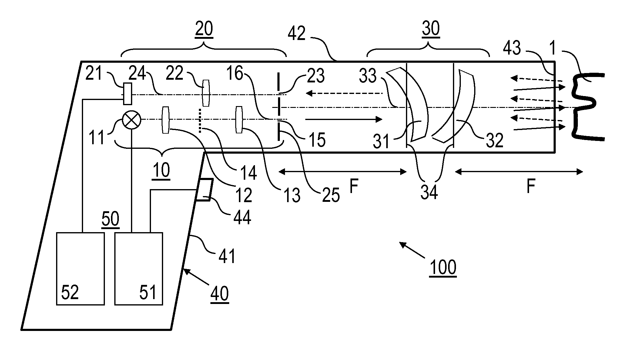
[0029]Embodiments of the invention are described in the following with particular reference to the telecentric configuration and the inventive surface reflection suppression. Known details of triangulation cameras and the use thereof, in particular the design of a camera casing, the selection of a light source and / or a detector camera, quantitative features, like the size and geometry of the illumination pattern or the magnification of the imaging optic, the coupling with a control device, the reconstruction of a shape of an object surface are not described here as they are known as such from prior art. Furthermore, particular reference is made to a triangulation camera device configured as a medical camera for medical imaging, in particular a dental camera for imaging a tooth surface. Again, reconstructing of a tooth surface shape and obtaining input data for prototyping a tooth filling are known as such from prior art. The invention is not restricted to the dental camera applicati...


PUM


Abstract

A triangulation camera device includes a light source device being adapted for generating illumination light to be directed onto an object under investigation and including a light source with an optical pattern generator and a first aperture being arranged along a first optical axis, a detector device being adapted for sensing reflection light reflected by the object and including a detector camera and a second aperture being arranged along a second optical axis, and an imaging optic having imaging lenses being adapted for imaging the illumination light onto the object and for collecting the reflection light, said imaging optic having a third optical axis, wherein the first, second and third optical axes are arranged in parallel and displaced relative to each other and the first and second apertures are arranged with a telecentric configuration relative to the imaging optic such that the illumination light and the reflection light are capable of forming a parallel illumination light bundle and a parallel reflection light bundle, resp., on the object side of the imaging optic, said illumination light bundle and said reflection light bundle having a predetermined projection angle, and the imaging lenses are tilted relative to the third optical axis such that surface reflections of the imaging lenses are directed toward ranges outside the second aperture.

Description

TECHNICAL FIELD[0001]The present invention relates to a triangulation camera device being in particular adapted for measuring of a surface of an object under investigation, like a medical object, e.g., a tooth or another part of a human body, or a workpiece. Furthermore, the present invention relates to a triangulation imaging method, in particular for investigating a surface of an object. Applications of the invention are present in medical imaging, in particular in intraoral dental imaging of a tooth surface, or in non-medical imaging, in particular in imaging of a workpiece surface.TECHNICAL BACKGROUND[0002]Triangulation cameras are adapted for illuminating an object and sensing reflection light reflected from the objects surface. The triangulation camera includes an imaging optic for imaging illumination light onto the object and for imaging reflection light reflected from the object on a detector camera. Triangulation cameras are simply used for obtaining an enlarged image of t...

Claims


Application Information

Patent Timeline
IPC IPC(8): H04N7/18G01B11/24A61B6/00
CPCA61B5/1077H04N7/183G01B11/25A61B5/4547
Inventor SCHMIDT, VOLKER
Owner BERLINER GLAS HERBERT KUBATZ
Why Eureka
Try Eureka